A CT scanner that aborts an exposure can point to a tube problem, but CT tube failure diagnosis should never begin and end with the error code. A tube-related fault may originate in the X-ray tube assembly, yet similar symptoms can be caused by the high-voltage generator, tube housing connections, cooling circuit, gantry control electronics, or an interlock condition. Replacing a costly tube without isolating the cause can extend downtime rather than resolve it.
For ISOs, biomedical departments, and imaging service providers, the objective is straightforward: determine whether the tube is the failed component, identify any contributing condition, and secure the exact replacement part before the scanner loses more productive time.
Start With the Failure Pattern
The fault history is often more useful than a single active error. Review when the issue occurs: at system startup, during warm-up, at the first exposure, only at higher kV or mA settings, or after a defined number of scans. Record the error text, numeric codes, scan protocol, tube loading condition, and whether the fault is repeatable.
A hard failure that occurs consistently at exposure enable may indicate a high-voltage, filament, rotor, or tube communication issue. An intermittent fault that follows a long scan sequence may instead point toward thermal management, marginal connections, or a component degrading under load. If image quality changes before the system begins aborting scans, that evidence matters. Streaking, increased noise, inconsistent output, arcing-related artifacts, or unexplained calibration failures can help narrow the investigation.
Do not assume that an error labeled "tube" identifies the tube itself. OEM software frequently reports the subsystem where a protection limit was reached, not a final component-level diagnosis.
Confirm Basic Operating Conditions First
Before evaluating the tube assembly, verify the conditions that allow it to operate. This reduces unnecessary tube replacement and prevents damage to a replacement component.
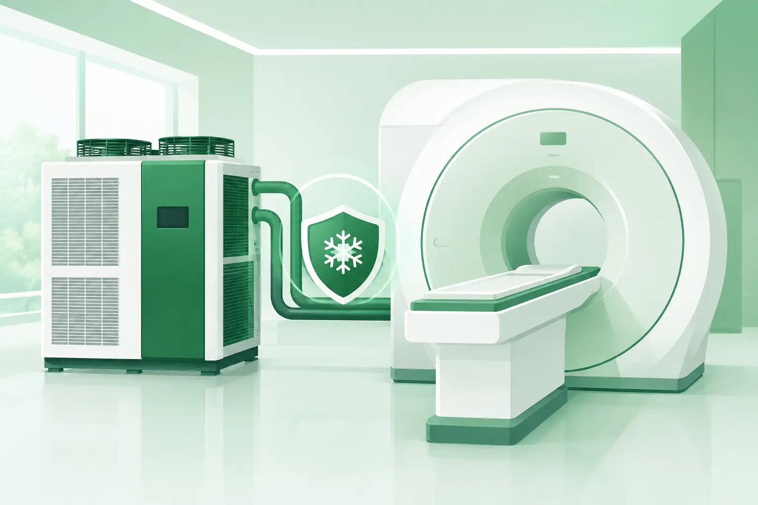
Check that the system is completing its required warm-up sequence and that no recent interruption, power event, software change, or gantry service preceded the fault. Review cooling status, coolant level where applicable, pump operation, flow alarms, heat exchanger performance, and temperature trends. A cooling issue may trigger tube protection faults after repeated exposures even when the tube itself remains functional.
Also inspect accessible connector interfaces, cable routing, gantry harnesses, grounding points, and signs of moisture, coolant residue, carbon tracking, or overheating. Follow manufacturer procedures and system lockout requirements. CT systems contain hazardous high-voltage circuits and stored energy. High-voltage measurements, insulation tests, and internal generator work belong only to qualified personnel using the specified service documentation and test equipment.
A quick visual inspection is not a substitute for diagnostics, but it can establish whether the fault followed a practical cause such as a disturbed connector after gantry work or a cooling-service issue.
Separate Tube Symptoms From Generator and Control Faults
Tube assembly indicators
A failing CT tube may show several patterns, depending on its design and failure mode. Filament-related problems can present as inability to establish or regulate tube current. Rotor faults may produce delayed readiness, abnormal spin-up behavior, rotor-speed errors, or exposure aborts. Vacuum degradation or internal arcing can produce unstable output, recurring high-voltage faults, unusual acoustic events, or image artifacts that worsen under load.
Tube age and workload provide context but not proof. High accumulated scan volume, frequent high-output protocols, trauma imaging, cardiac studies, or repeated extended acquisitions can accelerate wear. However, a tube with substantial use may be healthy, while a relatively recent replacement may fail because of cooling, generator, installation, or handling conditions.
Generator and high-voltage path indicators
The generator, high-voltage tank, cables, and associated control circuits can imitate a tube failure. A generator that cannot sustain commanded kV, a marginal high-voltage connection, or insulation breakdown in the high-voltage path may produce exposure inhibits, arc faults, or repeated trips. If logs show unstable kV regulation or a fault tied closely to generator status, investigate that path before condemning the tube.
Service software may provide commanded versus actual values for tube current, kV, rotor status, filament behavior, temperature, and exposure sequence states. The available data varies by OEM and scanner generation, but trend information is valuable. A consistent mismatch between command and feedback can identify where the sequence is failing.
Cooling and gantry control indicators
Cooling and control faults often reveal themselves through timing. A scanner that runs normally when cold but faults after multiple patients may have an inadequate thermal margin. A fault that appears while the gantry rotates, or only at certain positions, may point to rotating connections, slip-ring-related systems, harness movement, or gantry controls rather than the tube.
This is why a test exposure alone is rarely enough. Compare the fault against temperature, scan duration, gantry state, and power demand. The most useful diagnosis explains the whole pattern, not just one error message.
Use a Controlled Verification Sequence
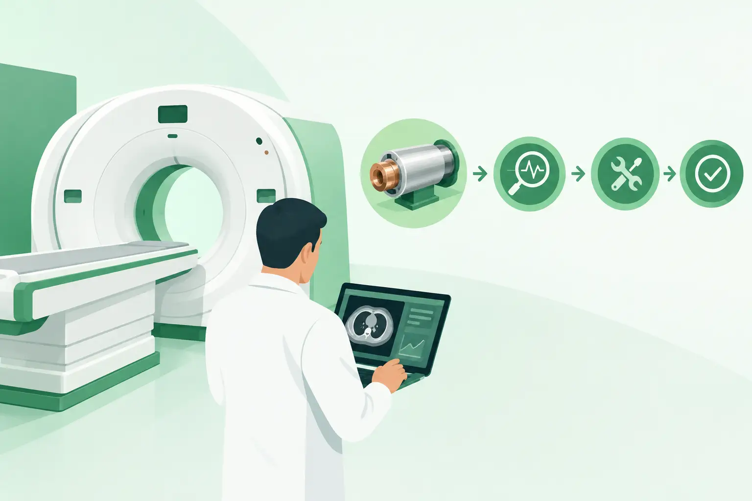
Once the initial evidence is collected, use the OEM-approved service workflow to verify the suspected subsystem. Begin with noninvasive checks and review system logs before moving toward component substitution or internal measurements. Clear fault history only after it has been documented, since recurring codes and sequence data may be needed to distinguish a primary fault from secondary protections.
Where the service documentation permits, controlled exposures at defined settings can help establish whether failure correlates with output demand. Avoid repeatedly forcing exposures through an unresolved high-voltage or cooling fault. Repeated attempts can create additional damage, obscure the original condition, and place personnel at risk.
If a known-good compatible component is available through an approved service process, substitution can be decisive. It must be a true match for the scanner configuration, tube housing interface, generator compatibility, focal spot requirements, cooling arrangement, and applicable software or calibration requirements. Similar-looking CT tube assemblies are not interchangeable merely because they fit the same OEM family.
What to Capture Before Sourcing a Replacement
A replacement request should be built around identification and failure evidence, not a general description such as "CT tube needed." The tube assembly label and OEM part number are the primary references. When labels are damaged or inaccessible, the scanner model, system serial number, existing tube serial number, housing part number, and photographs of identification labels can help cross-reference the correct item.
Provide the active and historical fault codes, a concise symptom description, whether the system can complete warm-up, and whether cooling or generator checks have been performed. Include any recent service activity involving the gantry, high-voltage components, cooling circuit, or software. These details help prevent a mismatch and allow the supplier to distinguish among revisions that may have different interfaces or compatibility requirements.
For legacy CT platforms, part-number-level verification is especially important. A discontinued assembly may have multiple revisions, exchange configurations, or regional variants. The fastest available unit is useful only if it is the correct unit.
Plan the Replacement as a System Event
Installing a tube assembly is not simply a swap. The required procedure can include mechanical alignment, cooling preparation, vacuum or leak checks where applicable, initialization, tube conditioning, calibration, and post-installation quality checks. Requirements differ substantially by OEM and CT generation.
Before scheduling installation, confirm what accessories, seals, coolant specifications, tools, calibration procedures, and qualified labor are required. If the original failure may have been driven by generator instability or insufficient cooling, correct that root condition first. Otherwise, the replacement tube is exposed to the same failure mechanism from its first scan.
For hard-to-find CT tube assemblies, Meditegic can support exact-match sourcing using OEM part numbers and system-specific details across current and legacy imaging platforms. That level of identification is what turns an urgent request into a usable replacement plan.
When the scanner is down, speed matters. But the better operational decision is to move quickly with documented fault evidence, verified compatibility, and a plan to address the condition that caused the protection fault in the first place.