A faint horizontal band on one chest image may be easy to dismiss. The same band appearing at the identical detector location on every exposure is a different operational problem. Effective DR artifact diagnosis separates patient, technique, and processing variables from a fault in the detector, grid, acquisition chain, or workstation before repeat studies accumulate or a working component is replaced unnecessarily.
For biomedical teams, ISOs, and imaging service providers, the objective is not simply to name the artifact. It is to establish where it originates, determine whether the issue is intermittent or progressive, and identify the exact service action required. That may mean recalibration, a grid inspection, a cable replacement, a detector repair, or sourcing an exact-match flat panel or control component for a legacy room.
Start DR Artifact Diagnosis With Pattern and Location
The first question is whether the artifact is fixed to the image receptor, fixed to anatomy, or changes with technique. This distinction removes a large amount of guesswork.
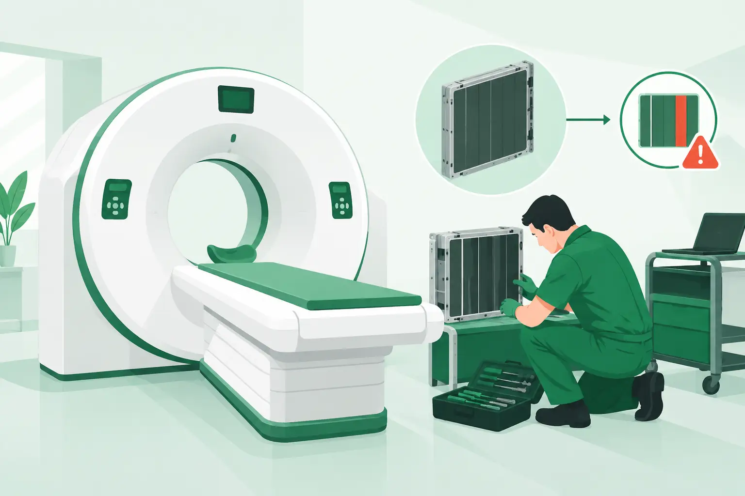
An artifact that stays in the same pixel coordinates across different patients, projections, and collimation settings usually points toward the detector or its correction data. Dead pixels, defective detector rows, gain non-uniformity, bad pixel maps, and panel electronics can all produce repeatable fixed-pattern defects. A line may be subtle at low exposure and more obvious in thicker anatomy, but its location remains stable.
An artifact that moves with anatomy is less likely to be a detector defect. It can result from clothing, skin folds, hair, jewelry, external objects, motion, or pathology. If it appears only on a particular exam type, do not assume the panel is failing until positioning accessories, technique charts, and room workflow have been reviewed.
Artifacts that change with SID, orientation, collimation, exposure field size, or grid use often point elsewhere. Grid cutoff, scatter-related degradation, exposure recognition errors, and processing behavior can mimic a detector issue. This is why one image is rarely sufficient evidence for a part decision.
Compare Raw and Processed Images
When the system permits access, compare the raw acquisition image with the processed image. A defect visible in raw data is upstream of image processing and deserves attention at the detector, panel electronics, detector cable, or acquisition hardware level. A defect visible only after processing directs the investigation toward the image-processing application, software configuration, exam protocol, LUT selection, or workstation.
This test is not universal. Some OEM platforms restrict raw-image access, and the service procedure differs across GE, Siemens, Philips, Canon/Toshiba, Fujifilm, Carestream, and other systems. Follow the applicable service documentation and preserve the original images before changing calibration files or processing parameters.
Classify the Artifact Before Troubleshooting
The visual pattern provides a useful starting point, but it is not a complete diagnosis. Similar-looking artifacts can have different causes depending on detector design, firmware level, grid configuration, and clinical application.
| Artifact pattern | Likely sources to investigate | Practical confirmation | | --- | --- | --- | | Fixed white or dark pixels, clusters, or lines | Detector element failure, row/column electronics, defective pixel correction map | Repeat a uniform-field exposure and confirm the defect remains in identical pixel coordinates | | Broad non-uniform shading | Gain or offset calibration issue, detector aging, panel damage, exposure-field inconsistency | Perform the OEM-specified flat-field or uniformity test | | Fine repetitive grid lines or moire | Stationary grid frequency, grid orientation, processing mismatch, failed moving grid | Compare exposures with and without the grid where permitted by procedure | | Edge clipping or missing image area | Exposure field recognition, collimation, incorrect exam protocol, processing software | Review raw image boundaries and acquisition settings | | Intermittent image loss, banding, or noise | Detector cable, connector, power supply, wireless communication, acquisition electronics | Correlate events with detector movement, battery state, cable position, and error logs | | Ghosting or lag | Detector exposure history, saturation, panel condition, calibration issue | Review sequence timing and perform the manufacturer-recommended lag test |
A uniform phantom or flat-field test is particularly valuable because it removes anatomy as a variable. Use consistent exposure factors, geometry, and detector orientation. If the system has a manufacturer-defined quality-control phantom and procedure, use that rather than inventing a local method. The goal is repeatable evidence that another technician or supplier can interpret.
Rule Out Grid and Technique Variables
Grid-related artifacts are frequently misidentified as detector defects. A stationary grid can create visible lines or moire when its frequency and orientation interact poorly with detector sampling. A moving grid can create artifacts if the mechanism does not travel correctly, if exposure timing is wrong, or if the grid is damaged or misaligned.
Grid cutoff produces a different appearance: density or brightness may fall off toward one side or across the image, often changing with tube angle, centering, SID, or grid orientation. In portable DR work, off-level positioning and grid alignment are common contributors. Before ordering a detector, inspect the grid, verify centering and alignment, and compare a controlled non-grid exposure if the clinical protocol and radiation-safety procedures allow it.
Technique also matters. Underexposure can make detector noise conspicuous, while excessive exposure can cause saturation or lag effects. Scatter, poor collimation, and processing choices may exaggerate an artifact that is present but clinically insignificant. A detector should be judged against the system's expected quality-control performance, not against a single difficult patient study.
Check the Detector, Cable, and Acquisition Chain
Once a fixed detector-side artifact is likely, work from the least invasive checks toward component-level repair. Review system messages and logs first. Error codes, detector serial identification faults, dropped frames, calibration failures, and communication events can narrow the investigation quickly.
For tethered panels, inspect the cable path, strain relief, connector condition, and any signs of intermittent movement-related failure. Repeated flexing can affect cables and connectors long before a detector is conclusively defective. Do not manipulate powered connectors outside approved service procedures, and do not substitute parts without confirming compatibility by OEM part number and revision.
For wireless detectors, inspect battery condition, charging contacts, access point communication, and whether the artifact occurs on more than one detector. A transmission failure may produce incomplete or corrupted image data, while a fixed pixel defect remains tied to the same receptor regardless of room or workstation.
If the room supports a known-good detector comparison, it can be decisive. Move the suspected detector to a compatible acquisition environment only when the OEM procedure permits it. If the defect follows the detector, the panel or its attached components become the leading suspects. If it remains with the room, investigate the generator interface, acquisition workstation, detector interface hardware, cabling, or software configuration.
Calibration Is a Service Action, Not a Guess
Offset and gain calibrations correct predictable detector response variation. They can resolve non-uniformity after a documented change in detector behavior, configuration, or service state. They cannot reliably repair physical panel damage, failed electronics, or a deteriorating detector array.
Treat calibration as a controlled intervention. Record the pre-calibration artifact, complete the OEM procedure under the specified conditions, and repeat the same quality-control exposure afterward. If the artifact disappears and stays absent through normal use, document the result. If it returns, becomes more extensive, or calibration repeatedly fails, the system needs deeper component evaluation.
Repeated calibration without evidence can delay a necessary repair and obscure the failure history. It may also consume valuable time when a busy imaging room needs a replacement detector, cable, control board, or power-related component to return to service.
Document Evidence That Supports Exact-Match Sourcing
A sourcing request is faster and more accurate when it contains more than a system model. DR assemblies vary by detector size, panel technology, OEM revision, firmware compatibility, connector style, and room configuration. A part that appears similar may not communicate correctly with the installed acquisition chain.
Capture the system manufacturer and model, detector manufacturer and model if separately labeled, complete OEM part number, serial number, software version when available, and the artifact's behavior. Include whether the defect is fixed or intermittent, whether it appears in raw images, calibration results, error codes, and clear sample images with patient information removed according to local policy.
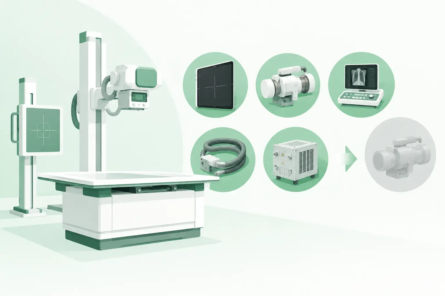
For hard-to-find flat panels, detector interface boards, acquisition electronics, cables, or grid components, this evidence allows a specialist supplier to cross-reference the requirement at the part-number level rather than offering a generic substitute. Meditegic supports this type of exact-match sourcing across current and legacy DR environments, where downtime often makes a vague request costly.
When to Remove the Room From Clinical Use
Not every artifact requires immediate shutdown. The decision depends on clinical visibility, repeatability, the exams performed, local quality policy, and whether the defect could obscure relevant anatomy. A small peripheral defect may be manageable under documented local guidance; a central line, broad non-uniformity, corrupted image data, or intermittent acquisition failure may not be.
Escalate promptly when image integrity is uncertain, when repeated exposures are occurring, or when the system shows electrical, communication, or detector-handling faults. Qualified personnel should perform service work involving detector internals, power supplies, generator interfaces, or high-voltage sections. The fastest recovery is usually the one based on evidence, not the first component that seems plausible.
A disciplined DR artifact diagnosis process turns a vague image-quality complaint into a defensible service decision. Preserve the images, test one variable at a time, and source against the verified part number when replacement is justified. That approach protects both clinical confidence and the uptime of a high-value imaging asset.