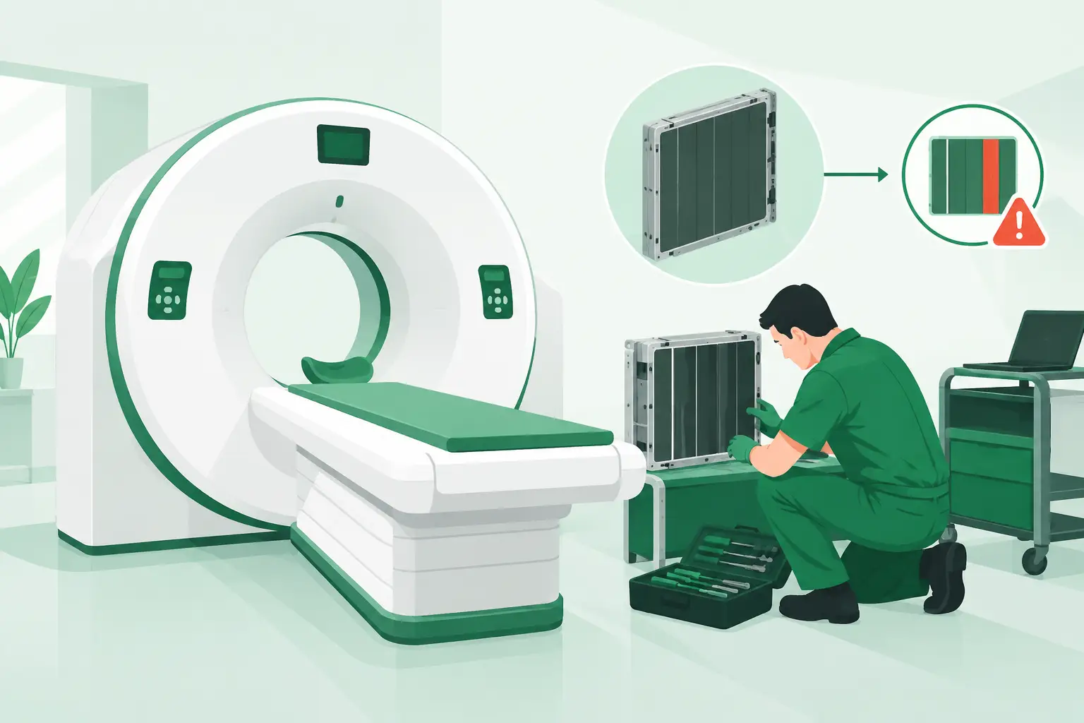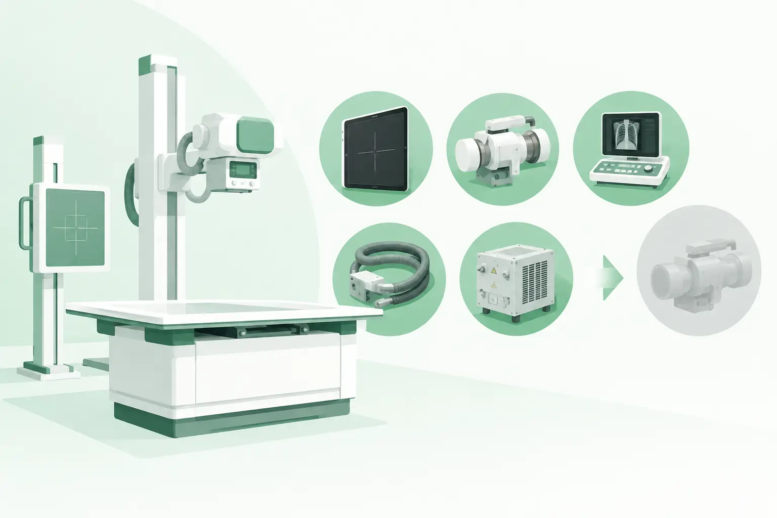
A cooling alarm during a booked MRI schedule is not a routine maintenance event. Solving MRI cooling failures starts with determining what is actually overheating, losing flow, or operating outside specification before a minor support-system fault turns into canceled exams, gradient derating, or a magnet-risk event.
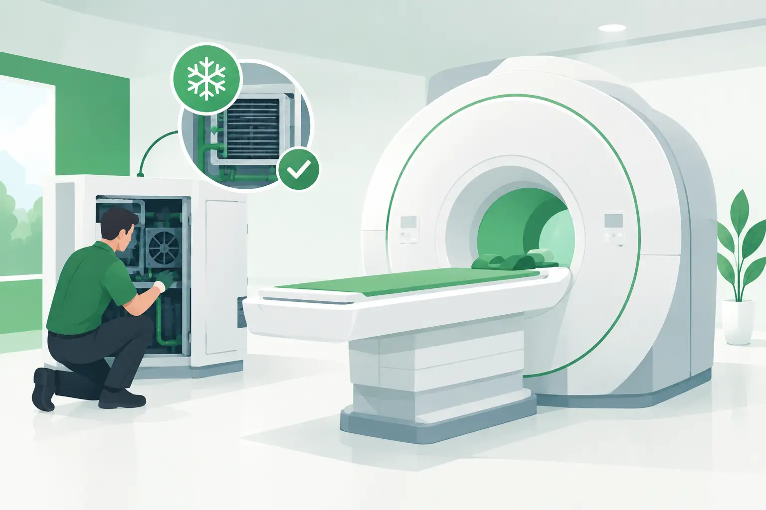
MRI cooling is not one system. Depending on the platform, it can include a closed-loop water circuit for gradient amplifiers and electronics, a chiller or facility-water interface, a compressor and cold-head assembly supporting the cryostat, cabinet fans, heat exchangers, pumps, sensors, valves, and control boards. A fault code may identify the affected loop, but it does not automatically identify the failed component.
For clinical engineering teams, ISOs, and imaging service providers, the practical objective is clear: isolate the failure quickly, protect the magnet and patient schedule, and obtain the exact replacement component without introducing a compatibility problem.
Start by Identifying the Cooling Circuit at Fault
The first question is whether the alarm concerns magnet refrigeration, gradient/electronics cooling, or room and cabinet heat rejection. These systems can affect one another, but they require different troubleshooting paths and carry very different operational risk.
A cryogenic cooling issue may involve the cold head, helium compressor, compressor adsorber, refrigerant circuit, pressure monitoring, or a communications fault between the refrigeration equipment and scanner controls. Symptoms can include elevated cold-head temperature, compressor alarms, abnormal pressure readings, increased helium boil-off indicators, or magnet-related warnings. These conditions require strict adherence to the OEM service procedure and escalation criteria. Do not treat a suspected cryostat or helium-management issue as a generic chiller repair.
A gradient cooling failure often presents differently. The scanner may report low coolant flow, high gradient temperature, chiller fault, pump fault, or an interlock that prevents scanning. On water-cooled systems, the root cause may be inadequate flow, a blocked filter or heat exchanger, low fluid level, poor coolant quality, a failed pump, a sticking valve, or a sensor providing an inaccurate reading. Ambient room temperature and restricted equipment ventilation can also push an otherwise marginal system into alarm.
Before ordering parts, verify the exact alarm text, subsystem designation, and time sequence. An intermittent flow warning that occurs only during high-duty sequences points to a different fault pattern than a permanent low-flow indication present at power-up.
Solving MRI Cooling Failures Through Fault Isolation
Good troubleshooting separates a true component failure from a condition that makes a healthy component appear defective. Replacing a pump without confirming suction conditions, fluid level, electrical supply, and flow feedback can waste critical time and leave the original fault unresolved.
Begin with the basic operating state. Confirm whether the scanner is in a controlled shutdown, limited-operating mode, or full interlock. Review recent service activity, facility work, power events, software changes, and prior alarms. A cooling problem that appears immediately after a water treatment visit, HVAC interruption, or chiller maintenance deserves a different investigation than a gradual rise in operating temperature over several weeks.
Then inspect the system against the applicable service documentation. Check coolant level where the design permits, visible leaks, hose condition, quick-connect seating, filter differential condition, pump noise, fan operation, condenser cleanliness, and equipment-room temperature. Verify supply voltage, breaker status, contactor condition, and any local controller display. A pump may be mechanically sound but unable to start because of a failed relay, power supply, drive board, or safety interlock.
Sensor faults deserve particular attention. Temperature, pressure, flow, and level sensors can drift, fail open, or develop connector and harness issues. If measured physical conditions do not match the value reported to the console, do not assume the cooling circuit itself is defective. Compare readings using approved methods and check the sensor, cable, connector pins, and associated input board before replacing larger assemblies.
Treat Flow Alarms as a System Problem
Low-flow alarms are frequently blamed on the circulation pump. Sometimes that is correct, particularly when a pump is noisy, seized, electrically open, or unable to maintain specified pressure. But restricted flow can also result from contamination, partially closed valves, air in the circuit, kinked lines, clogged strainers, fouled heat exchangers, or a defective flow switch.
Coolant chemistry matters as well. Incorrect fluid concentration, incompatible additives, or neglected maintenance can contribute to corrosion, deposits, sensor contamination, and reduced heat transfer. The right corrective action depends on the system design and OEM-approved coolant specification. Flushing or changing fluid without confirming that specification can create material-compatibility issues or introduce air that complicates recovery.
When a chiller is involved, distinguish between a chiller that has failed and one that is responding properly to a downstream restriction or excessive thermal load. Review inlet and outlet temperatures, flow status, compressor operation, fan performance, condenser condition, and any active chiller-specific faults. In warm climates or poorly conditioned equipment rooms, heat rejection may be the limiting factor rather than the MRI cooling hardware itself.
Do Not Bypass Protective Interlocks
A cooling interlock exists to prevent damage to high-value components. Bypassing a flow switch, temperature input, or controller alarm to finish a scan list can expose gradient amplifiers, power electronics, or magnet-support equipment to conditions outside their safe operating range.
The same principle applies to repeated resets. A reset can be appropriate after an approved corrective action, but repeated cycling without fault isolation may obscure diagnostic evidence and increase stress on pumps, compressors, contactors, and power components. Record the alarm history and operating conditions before clearing codes whenever possible.
Build a Part Request That Can Be Quoted Correctly
Once the failed assembly is identified, sourcing accuracy becomes the next uptime issue. MRI cooling parts are often configuration-specific even when the equipment family name is the same. A pump, heat exchanger, chiller controller, cold-head cable, sensor, power supply, or control board may vary by scanner model, magnet configuration, software revision, regional electrical configuration, or equipment generation.
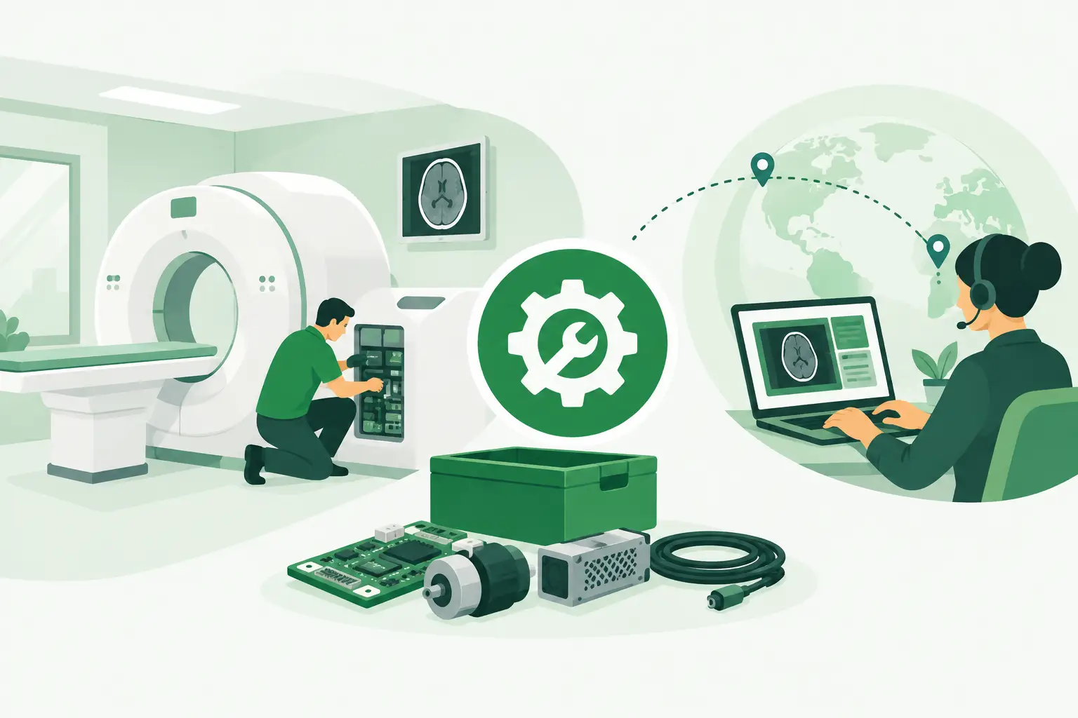
A useful request should include the OEM part number whenever available, the scanner model, subsystem name, serial number, fault description, and clear photographs of labels and connectors. If the part number is unreadable, include dimensions, hose or fitting details, voltage and current ratings, connector pin count, and any board revision markings. These details allow a supplier to cross-reference the component at the part-number level rather than relying on a broad description such as “MRI chiller pump.”
For boards and controller modules, identify whether the unit has been exposed to moisture, coolant leakage, overheating, or an electrical event. A replacement board may fail quickly if the underlying short, connector corrosion, or unstable supply remains in place. For pumps and valves, note the fluid used and whether debris was found in filters or strainers. The replacement decision should be paired with correction of the condition that caused the failure.
Meditegic supports this type of urgent, exact-match sourcing across MRI and other diagnostic imaging modalities, including hard-to-find cooling components, electronics, and subsystem parts for current and legacy platforms. Availability can depend on the part’s condition, revision, and location, so part-number accuracy is the fastest route to a workable quotation and compatible replacement.
Plan the Return to Service, Not Just the Repair
Restoring power and clearing an alarm is not the same as confirming recovery. After a cooling repair, qualified personnel should verify stable temperatures, pressure or flow values, absence of leaks, pump and fan behavior, and alarm-free operation through an appropriate functional test. For gradient-related cooling, confirm performance under the type of imaging load that previously triggered the fault, while following approved service limits.
For magnet refrigeration issues, return-to-service decisions should be governed by OEM procedures and qualified MRI service personnel. Trend data, helium indicators, compressor behavior, and cryostat status may need observation beyond the initial repair window. The trade-off is straightforward: extending verification may affect the schedule, but releasing an unstable cooling system can create a longer and more expensive outage.
It also helps to preserve the failed part, alarm history, and service notes until the repair is validated. These records improve root-cause analysis and make future sourcing faster if the same failure pattern returns. On aging MRI platforms, identifying recurring cooling components before they become urgent can reduce exposure to discontinued or long-lead replacements.
The most effective response to an MRI cooling alarm is disciplined rather than improvised: protect the system, isolate the correct circuit, validate the failed component, and source the exact part with enough technical detail to install it once and return the scanner to dependable operation.