A fluoroscopy intensifier replacement is not a generic swap. An image intensifier affects image brightness, contrast, field coverage, and dose-management performance across the entire fluoroscopy chain. Ordering the wrong assembly, or replacing an intensifier before confirming the actual fault, can extend downtime and create a second service event.
For C-arm, R/F, and legacy fluoroscopy systems still in productive clinical use, the correct approach starts with fault isolation and ends with documented acceptance testing. The replacement component must match the system at the OEM part-number level, while its condition and optical performance must be appropriate for the application.
When Fluoroscopy Intensifier Replacement Is the Right Repair
Image intensifiers degrade over time. Their failure is often gradual rather than absolute, which can make diagnosis less straightforward than a complete no-image condition. Common symptoms include reduced brightness, uneven illumination, persistent image artifacts, edge distortion, poor contrast, or a visible loss of detail that cannot be corrected through normal system adjustments.
Output phosphor wear can produce localized burn-in or ghosting, particularly on systems used repeatedly with static anatomy or collimated fields. Input phosphor damage, vacuum loss, internal contamination, and aging electron optics can also affect image quality. A dark image may point to an intensifier issue, but it can also originate in the X-ray generator, high-voltage supply, camera chain, optical distribution components, image processor, monitor, or system calibration.
Before authorizing a replacement, compare current performance with the system's prior baseline where available. Review error logs, verify power and interconnect integrity, inspect connectors and cables, and determine whether the issue appears across all field-of-view modes. A fault that changes with magnification mode can provide useful direction, but it is not by itself proof that the intensifier has failed.
Verify Compatibility Before Ordering an Intensifier
The most expensive mistake in fluoroscopy intensifier replacement is treating tube size as the primary compatibility criterion. A 9-inch or 12-inch image intensifier designation describes only part of the picture. Mechanical mounting, electrical interfaces, optical output configuration, field-of-view geometry, housing dimensions, and system-specific calibration requirements can differ substantially among models.
Start with the OEM part number from the installed component whenever possible. Record the equipment manufacturer, system model, serial number, and the full part number including suffixes, revisions, and any label codes. Clear photos of the intensifier label, connector arrangement, mounting points, and housing are valuable when the label is incomplete or the original number is discontinued.
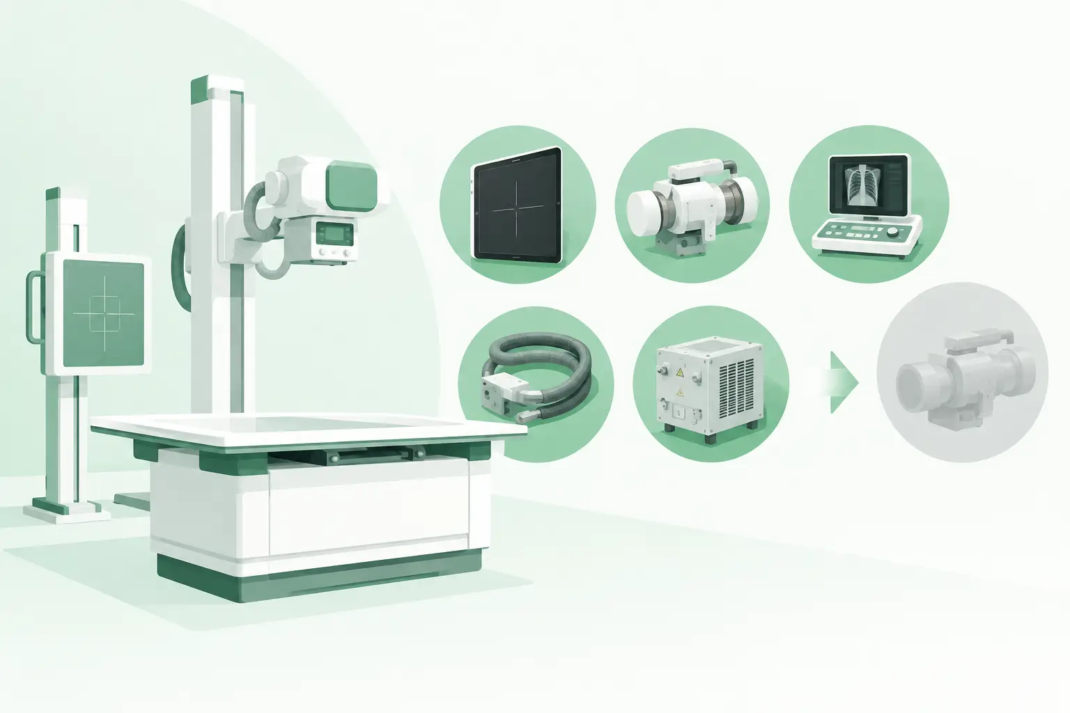
A qualified sourcing review should also confirm whether the requested item is the complete image intensifier assembly or a related component. On some systems, the reported "intensifier problem" may involve the camera, optical lens assembly, distributor, power supply, or a housing-mounted accessory. These are not interchangeable categories, and each has different failure modes and compatibility requirements.
Details That Must Match
For an exact replacement, service teams should verify the following technical details before a purchase order is released:
- OEM manufacturer and exact equipment model, including system generation
- Original intensifier part number, revision, and serial-number information when available
- Input diameter and supported field-of-view modes
- Mechanical mounting pattern, housing configuration, and connector type
- Optical output format and compatibility with the installed camera or imaging chain
- Electrical requirements, cable routing, and any system-specific calibration procedure
This information is especially important on discontinued fluoroscopy platforms. An alternate part may be physically similar yet require a different mounting bracket, cable assembly, optical adapter, or software configuration. A workable substitute should be identified as a verified cross-reference, not assumed from appearance.
Choose the Right Condition for the System and Workload
A used or refurbished image intensifier can be a practical option when a system is out of OEM support or a replacement is needed quickly. However, condition must be evaluated in operational terms, not only by whether the unit powers on or produces an image.
For a refurbished intensifier, ask how image performance was evaluated. Relevant considerations include brightness uniformity, contrast, distortion, image lag, field-of-view operation, output screen condition, physical housing integrity, and connector condition. The appropriate acceptance standard depends on the equipment's clinical role, utilization level, and the facility's established quality-control process.
A lower-cost component with visible burn-in or nonuniformity may not be suitable for a frequently used fluoroscopy room, even if it is functional. Conversely, a verified used replacement may be a sensible continuity solution for a lower-volume legacy C-arm where the alternative is extended outage or premature system retirement. The decision depends on application requirements, not price alone.
Plan the Replacement as a System-Level Service Event
Installing the intensifier is only one part of the work. The system must be returned to safe, repeatable imaging performance by personnel qualified to service fluoroscopic equipment. Follow the equipment manufacturer's service documentation, electrical safety procedures, and radiation safety requirements throughout the repair.
Before removal, document the installed assembly and cable routing. Inspect related hardware for damage, including mounting brackets, locking mechanisms, cable strain relief, optical couplings, and protective housings. A worn connector or damaged cable can compromise the replacement component and obscure the original fault.
After installation, the imaging chain requires functional verification and calibration as specified for that model. This may include brightness and contrast adjustment, field-of-view verification, geometric distortion review, automatic brightness control checks, image processing confirmation, and dose-related performance testing. Any work involving the fluoroscopy chain should be followed by the facility's required quality-control and radiation-safety acceptance process before clinical use resumes.
Do not judge a replacement solely by a single static image. Test each available mode and field size, review image behavior during fluoroscopy, and confirm that the unit responds predictably under normal operating conditions. If a system uses stored protocols or modality-specific presets, verify those as well.
Reduce Downtime With Better Sourcing Information
When an intensifier fails, procurement speed matters, but incomplete information slows the process. Sending only the system model often leads to avoidable back-and-forth because multiple intensifier configurations may have been installed across the same product family.
The strongest request for quote includes the exact part number, equipment details, symptom description, desired condition, destination, and timing requirement. If the original part is unavailable, the supplier can then investigate cross-references, compatible revisions, related assemblies, and available alternatives without guessing.
This is where a specialist imaging-parts supplier adds practical value. Meditegic supports part-number-level sourcing for difficult-to-find fluoroscopy and C-arm components across current and legacy OEM platforms, including used and refurbished options when appropriate. For service organizations maintaining mixed fleets, access to a broad sourcing network can be more useful than a catalog limited to currently supported equipment.
Avoid the Most Common Replacement Delays
Several avoidable issues repeatedly turn a straightforward repair into an extended outage. The first is ordering from a partial number without confirming suffixes or revisions. The second is replacing the intensifier when the fault actually sits elsewhere in the imaging chain. The third is overlooking accessories and interfaces that are not included with the replacement assembly.
Another common delay occurs after delivery: the part is installed, but calibration tools, service documentation, or qualified support have not been arranged. Confirm the complete service plan before the component arrives, particularly for remote sites or systems with limited local technical coverage.
A precise fluoroscopy intensifier replacement protects more than a single repair budget. It keeps a high-value imaging asset available, reduces repeat service calls, and gives the clinical team confidence that image performance has been checked rather than assumed. The fastest path back to operation is usually the one that begins with an exact part number, a verified diagnosis, and a replacement matched to the full imaging system.