A control board can look correct, carry a familiar OEM logo, and still be the wrong replacement. In diagnostic imaging, imaging PCB identification is the process that separates a potentially compatible-looking board from an exact, installable match for a specific system configuration. That distinction matters when a CT, MRI, fluoroscopy, ultrasound, or mammography system is down and every sourcing decision affects return-to-service time.
For biomedical teams, ISOs, and imaging equipment refurbishers, a board request that says only “Siemens power PCB” or “GE control board” usually leaves too much uncertainty. Major OEMs used multiple board generations, revisions, firmware configurations, and connector layouts across systems with similar names. Accurate identification turns a vague request into a sourceable component requirement.
What Imaging PCB Identification Must Establish
A printed circuit board is rarely identified by one visible label alone. The primary OEM part number is the strongest starting point, but it should be evaluated with the board’s revision, assembly number, system application, and physical configuration. A board can contain several numbers: a bare-board fabrication number, a board assembly number, a serial number, a vendor code, and an internal revision identifier. They do not carry the same sourcing value.
The number printed on the PCB substrate may identify only the unpopulated board design. The number on a white OEM label or barcode label may identify the fully assembled, serviceable replacement unit. For sourcing purposes, the assembly-level part number is generally the more useful reference, particularly when the board includes programmed devices, calibrated components, or factory-installed hardware.
The identification process should establish four things: the exact OEM and modality, the system and subsystem where the board operates, the orderable part number and revision, and the configuration details that affect interchangeability. Without all four, a supplier may locate a similar component that cannot be installed or will not communicate correctly with the system.
Why Similar Boards Create Expensive Delays
Imaging systems are built around tightly coordinated electronics. A gantry control board, detector interface PCB, high-voltage control board, MRI gradient component board, or ultrasound beamformer board may depend on a specific software release, harness arrangement, or companion assembly. Connector positions and component populations can differ subtly between revisions.
This is especially common in legacy platforms. An OEM may retain a board family name across years of production while changing firmware, memory devices, power regulation, or interface circuitry. The result is a board that appears nearly identical in a photo but has a different suffix or revision code. Installing an incorrect board can lead to boot faults, communication errors, calibration failures, or additional troubleshooting time.
There is also a practical sourcing risk. If a request is matched only by equipment model, a buyer may receive multiple offers for boards that are not equivalent. Reviewing each option after quotation prolongs downtime and can consume the time of a field engineer who needs an actionable replacement, not a list of possibilities.
A Practical Process for Imaging PCB Identification
Start with the system and the failed function
Document the OEM, complete system model, modality, and affected subsystem before removing or sourcing the board. “Philips C-arm” is not enough context. Identify the relevant cabinet, gantry, generator, detector, table, workstation, RF chain, or console section. Include the failure symptom when available, such as no gantry initialization, loss of detector communication, table motion fault, or power supply interlock error.
Symptoms do not prove that the PCB is defective. They do, however, help confirm whether the requested board belongs to the correct functional path. A power board and a communications board may both be present in the same rack, but they solve very different service issues.
Capture every label before cleaning or packing
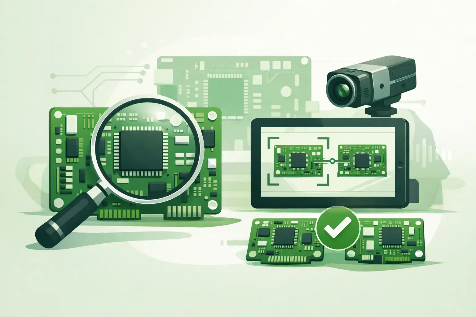
High-resolution photographs are often the fastest way to resolve ambiguity. Photograph the front and rear of the board, all labels, barcode stickers, edge connectors, jumpers, heat sinks, and any daughterboards. Take a wider photo showing the board’s installed location if access permits.
Record every legible number exactly as printed, including spaces, hyphens, prefixes, and suffixes. Do not assume that a revision letter is cosmetic. On imaging electronics, a suffix can indicate a different hardware build or an approved replacement relationship.
If a label is damaged, partial numbers still help. A clear photo of connector layout, board dimensions, component placement, and mounting points may allow an experienced sourcing specialist to cross-reference the assembly. However, visual matching should support a part-number match, not replace it when an OEM identifier is available.
Distinguish part number, serial number, and revision
Serial numbers track an individual unit. They are useful for traceability but do not normally identify an interchangeable replacement. Revision codes describe a version of the assembly. They may be printed as REV, ECN, dash number, or another OEM-specific format.
A useful request separates these fields rather than combining them into one string. For example, provide the assembly part number, revision, serial number, and any secondary label number as distinct entries. This prevents a serial number from being mistaken for the required orderable part number.
Check for programmed or paired components
Some PCBs are not simple plug-in replacements. They may contain firmware, programmable logic, calibration data, license-dependent functions, or paired settings tied to another system component. Detector electronics, workstation interface boards, motion-control assemblies, and modality-specific acquisition boards can require particular attention.
The right question is not only “Does this board fit?” It is also “What must be verified before installation?” Depending on the platform, that may include firmware level, revision compatibility, programmed memory, configuration switches, or the need for post-installation calibration. A qualified service professional should follow the applicable OEM service documentation and system safety procedures.
Information That Produces a Faster, Cleaner Quote
The strongest sourcing request combines precise identification with enough operational context to validate the match. Include the OEM, system model, modality, board part number, revision, clear photos, and a brief description of where the board is installed. If the original board is unavailable, include photographs of the vacant slot, mating connectors, and the associated module labels.
It also helps to state whether the requirement is for an immediate field repair, a planned replacement, or a spare for an aging system. The technical identification remains the same, but availability and acceptable replacement paths can differ. For an urgent repair, an exact board revision may be required. For a planned spare, a documented superseding assembly may be acceptable if compatibility has been confirmed.
When sourcing used or refurbished boards, ask about the condition classification, test status, exchange requirements if applicable, and whether the quoted item matches the stated part number and revision. “Compatible” should never be accepted as a substitute for clarification. It may mean an approved OEM cross-reference, or it may simply mean the board shares a product family.
Common Identification Errors to Avoid
The most frequent error is ordering from a generic description rather than the board label. The second is relying on a bare-board number when the serviceable assembly number is present elsewhere. Another common issue is omitting the revision suffix because the base number appears to match.
Teams also lose time by sending unreadable photos taken through reflective anti-static bags or by photographing only one side of the assembly. If a barcode label is present, photograph it straight on and include a second image of the complete board. This gives the sourcing team both machine-readable data and a visual reference for connectors, shielding, and installed components.
Finally, do not assume a board is failed solely because it is associated with a displayed error code. Power quality, cabling, cooling faults, interlocks, software state, and upstream modules can produce similar symptoms. Confirming the diagnostic path before procurement reduces unnecessary returns and repeat downtime.
When Cross-Referencing Becomes Essential
Cross-referencing is particularly valuable for end-of-life imaging systems, acquired product lines, and assemblies that have been replaced by an updated OEM number. A source may list a board under an older number, a revised number, or a manufacturer-specific internal reference. The ability to connect those records depends on detailed identifiers and modality knowledge.
For example, a control PCB from a GE Healthcare system should not be matched only to the brand and platform family. Its subsystem, board revision, connector format, and documented replacement history determine whether it is appropriate. The same principle applies across Siemens Healthineers, Philips, Canon/Toshiba, Hologic, Fujifilm, Hitachi, Carestream, and other current or legacy imaging platforms.
Meditegic works from part-number-level requirements across diagnostic imaging modalities, which is particularly useful when the needed component is discontinued, difficult to locate, or represented by multiple legacy references. The more complete the identification package, the more confidently a board can be matched through available inventory and global supplier channels.
A clear board label, complete revision data, and useful photographs may take minutes to collect. For an imaging system waiting on a hard-to-find replacement, that preparation can prevent days of avoidable back-and-forth and move the repair toward a correct first installation.