An MRI scanner can pass daily system checks and still produce images with localized signal loss, elevated noise, or an intermittent channel error. In those cases, MRI coil testing is not a generic quality-control task. It is the practical process of determining whether the RF coil, its cable, connector, interface, or scanner receive chain is responsible before a service team commits time and budget to the wrong repair.
For biomedical departments, ISOs, and imaging service providers, the objective is clear: isolate the fault quickly, preserve diagnostic image quality, and secure the correct replacement component if the coil has failed. That requires more than connecting a suspected coil and looking for an error message.
What MRI Coil Testing Needs to Confirm
An RF coil is both an imaging component and a tuned electronic assembly. Depending on its design, it may contain multiple receive elements, preamplifiers, detuning circuits, PIN diodes, cable assemblies, identification electronics, and channel-specific interfaces. A failure in any of these areas can cause a complete coil rejection, but more often it causes a partial and clinically significant loss of performance.
Effective testing should answer three questions. First, is the image artifact repeatable and specific to one coil or receive channel? Second, does the fault follow the coil when it is moved to a known-good connector or compared against a known-good coil? Third, is the coil economically repairable, or is an exact-match replacement the faster route to restoring operation?
The answer depends on the coil type and scanner architecture. A simple extremity coil may be straightforward to compare with another compatible unit. A multi-channel head, body, breast, spine, cardiac, or surface array coil can involve several independent elements and more complex channel mapping. A passing overall scan does not prove that every element is performing correctly.
Start With the Image and Error History
The first evidence is usually in the image, not on the workbench. Review recent studies for patterns such as a dark region, reduced signal-to-noise ratio, asymmetric shading, zipper-like noise, dropout in one anatomical area, or artifacts that appear only in certain positions. Compare images from the affected coil with an appropriate known-good coil and use the same protocol whenever possible.
System logs and service error codes add useful context. Errors involving coil recognition, channel initialization, detuning, preamplifier communication, or receive-path overload can point toward the coil or its interface. They are not definitive on their own. A damaged scanner-side connector, contaminated contact, failed receive channel, or software configuration issue can generate symptoms that resemble a coil failure.
Document the scanner model, coil name, coil serial number, connector position, reported errors, affected channels, and observed image behavior. This record helps prevent a common source of delay: sourcing a replacement based only on a broad description such as “Siemens head coil” or “GE body array.” Exact part-number and revision verification matter because similarly named coils may use different channel counts, connectors, patient supports, or compatibility configurations.
A Practical MRI Coil Testing Workflow
Testing should follow the scanner manufacturer’s service documentation and be performed by qualified personnel. RF coil assemblies and MRI system interfaces are not appropriate for improvised electrical measurements while connected to the scanner. The goal is to use controlled comparisons and approved procedures without risking the coil, system electronics, or patient safety.
1. Inspect the Physical Assembly
Begin with the visible and mechanical condition of the coil. Check the housing for cracks, loose sections, impact damage, fluid ingress, worn patient-contact surfaces, and damaged latches or positioning hardware. Examine the cable along its full length, especially at strain-relief points near the coil body and connector. Intermittent conductors often fail where repeated bending has stressed the cable.
Inspect connector pins, keying features, locking mechanisms, and contact surfaces. Bent, recessed, corroded, or contaminated contacts can produce intermittent recognition or channel faults. Do not assume that a clean-looking connector is electrically sound, but do not overlook it either. Connector damage can make a functioning coil appear defective.
2. Run the Approved Recognition and Quality Tests
Use the scanner’s approved coil check, service mode, phantom scan, and quality-assurance routines for that model. These tests can identify recognized elements, active channels, noise behavior, and image uniformity. When available, compare channel-level results against the expected configuration for the coil.
A controlled phantom scan is especially useful because it removes patient positioning and anatomy from the evaluation. Keep sequence parameters, coil placement, and phantom position consistent between the suspect coil and the known-good comparison coil. A repeatable localized signal deficit is more actionable than a subjective impression that the image “looks weak.”
3. Swap One Variable at a Time
The most reliable field method is controlled substitution. If a known-good compatible coil is available, test it on the same scanner port using the same protocol. If the replacement coil performs normally, the suspect coil becomes the primary concern. If the problem remains on the same port, investigate the scanner-side connector and receive-chain path.
Where the system and service procedure permit, changing the interface location can help determine whether the fault follows the coil or the port. Avoid changing multiple variables at once. Replacing a coil, moving ports, changing software settings, and selecting a different sequence in one test may restore an image, but it will not establish the cause.
4. Use Bench Testing as Evidence, Not a Shortcut
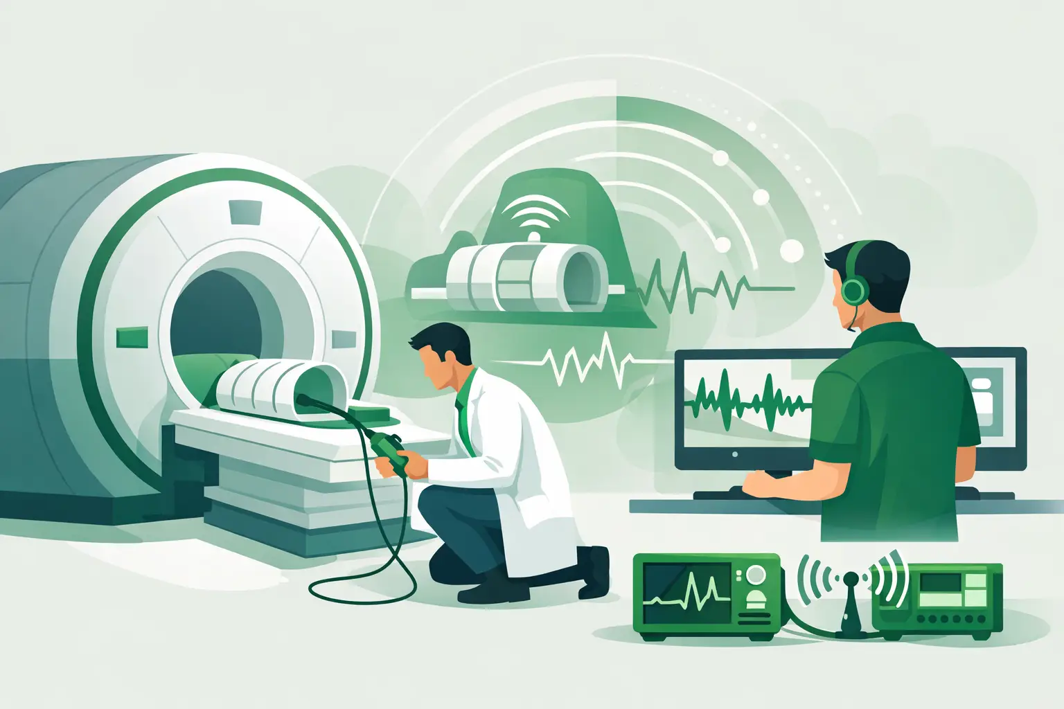
Specialized coil test equipment can evaluate cable continuity, element behavior, tuning characteristics, detuning performance, and preamplifier-related issues. These measurements are valuable when performed by a qualified repair facility with the correct fixtures and specifications for the coil design.
Bench results must be interpreted in context. A cable may test correctly at rest but fail under flexing. An element may appear acceptable outside the scanner yet show instability only when the coil is loaded or positioned. Conversely, a scanner-side issue can lead teams to condemn a coil that is electrically functional. The most defensible diagnosis combines physical inspection, controlled scanner testing, and appropriate bench evaluation.
Common Failure Modes and Their Symptoms
Cable fatigue and connector damage are common because coils are handled, repositioned, cleaned, and stored repeatedly. Their symptoms are often intermittent: the coil works in one position, fails after movement, or produces errors that clear after reconnecting. Intermittent faults should be treated seriously even if the coil returns to service temporarily. They tend to recur at the worst possible time.
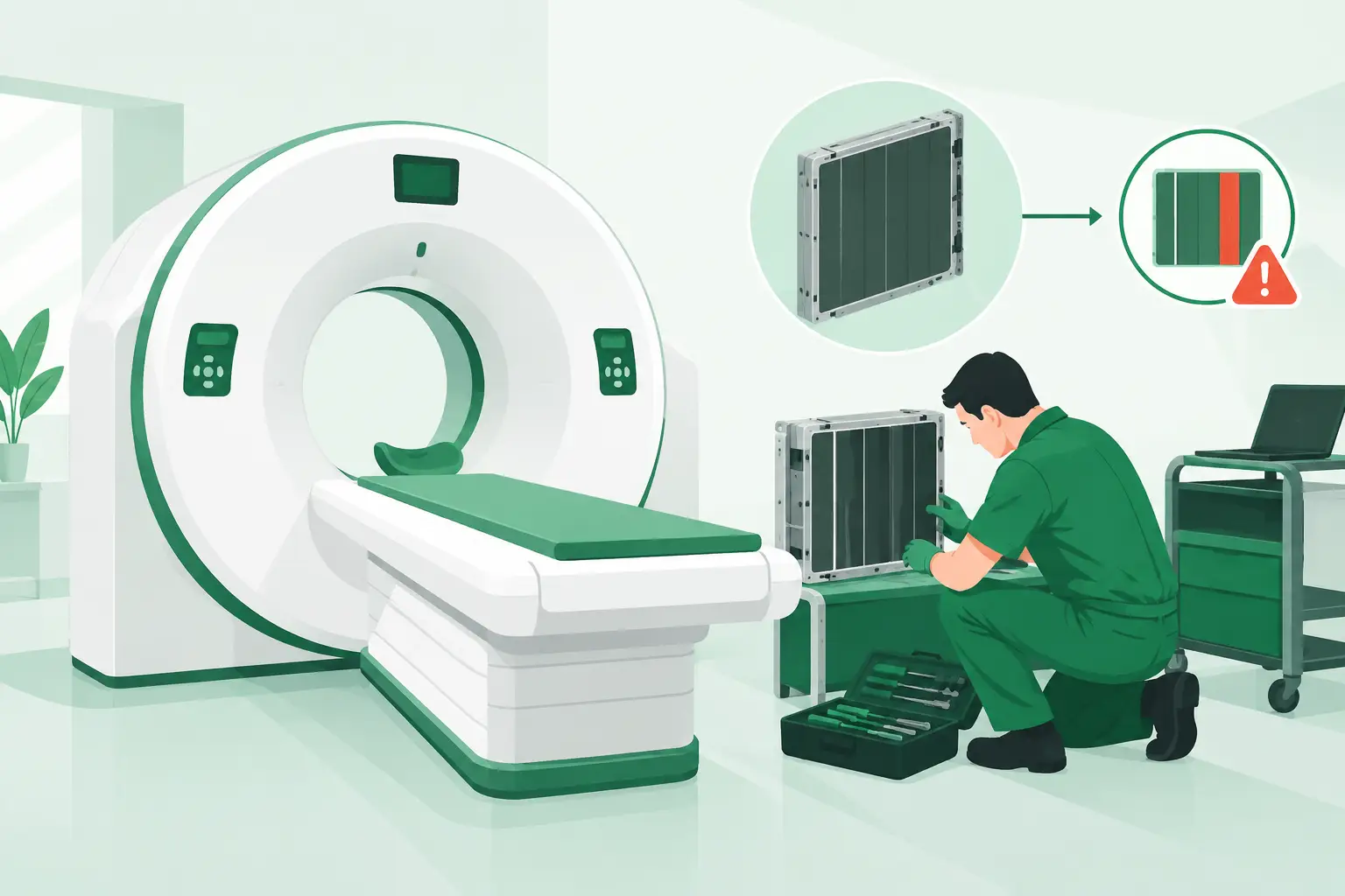
Receive-element or preamplifier failures more often create localized low signal, increased noise, or a missing region within the coil’s normal coverage area. In multi-channel arrays, one failed element may not stop the scan, but it can compromise image quality enough to affect clinical use.
Detuning-related faults can cause more complex behavior and require careful evaluation under approved procedures. Coil identification or communication failures may prevent selection entirely, trigger a system error, or cause the scanner to recognize a coil incorrectly. These symptoms can arise from identification electronics, connector contacts, cable conductors, or the scanner interface.
Repair or Replace: Make the Decision Around Uptime
Repair can be sensible when the fault is clearly limited to a serviceable cable, connector, housing component, or identified electronic assembly and a qualified provider can return the coil within the required timeframe. It may be less attractive when there is repeated intermittent behavior, unknown internal damage, multiple failed channels, or a long repair queue.
Replacement is not simply a matter of finding a coil with the same clinical name. Confirm the OEM part number, revision or model designation, channel configuration, connector type, compatible MRI platform, and required accessories or positioning components. For legacy GE Healthcare, Siemens Healthineers, Philips, Canon/Toshiba, and other OEM platforms, documentation may be incomplete and inventory may be fragmented across regions. That is where part-number-level sourcing prevents costly compatibility mistakes.
Meditegic supports this process by locating used, refurbished, and select new MRI RF coils and related imaging parts through a global supplier network. A clear fault record and exact part number allow a sourcing request to move faster than a broad equipment description, particularly when the failed coil is discontinued or difficult to locate.
Keep a Known-Good Reference Coil Available
For high-utilization MRI services, a compatible reference coil is one of the most useful diagnostic assets in the department. It reduces uncertainty during troubleshooting and can serve as temporary operational coverage while a failed coil is evaluated, repaired, or replaced. The right backup depends on exam volume and clinical mix, but the principle is consistent: a verified comparison unit shortens diagnosis.
When an image-quality complaint first appears, capture the evidence before it becomes an intermittent mystery. Record the affected coil, port, sequence, image pattern, and system message, then test methodically. That discipline turns MRI coil testing from a trial-and-error exercise into a faster path back to dependable scanning.