A scanner can complete its startup checks and still be unable to support a scheduled exam because of one component at the patient interface: the RF coil. MRI coils directly affect signal-to-noise ratio, anatomical coverage, image uniformity, workflow, and the range of exams a site can perform. When a coil fails, the consequence is rarely limited to a minor image-quality issue. It can mean canceled studies, repeat scans, patient rescheduling, and an imaging asset operating below its clinical capability.
For biomedical teams, ISOs, and MRI service providers, the practical challenge is not simply finding “an MRI coil.” It is confirming the exact coil configuration, connector arrangement, system compatibility, and part number needed to return a specific scanner to service.
What MRI Coils Do
MRI RF coils are antennas tuned to the scanner’s operating frequency. They transmit radiofrequency energy, receive the faint signal emitted by tissue after excitation, or perform both functions depending on the coil design and MRI platform. Their purpose is to place sensitive receiving elements as close as possible to the anatomy being scanned.
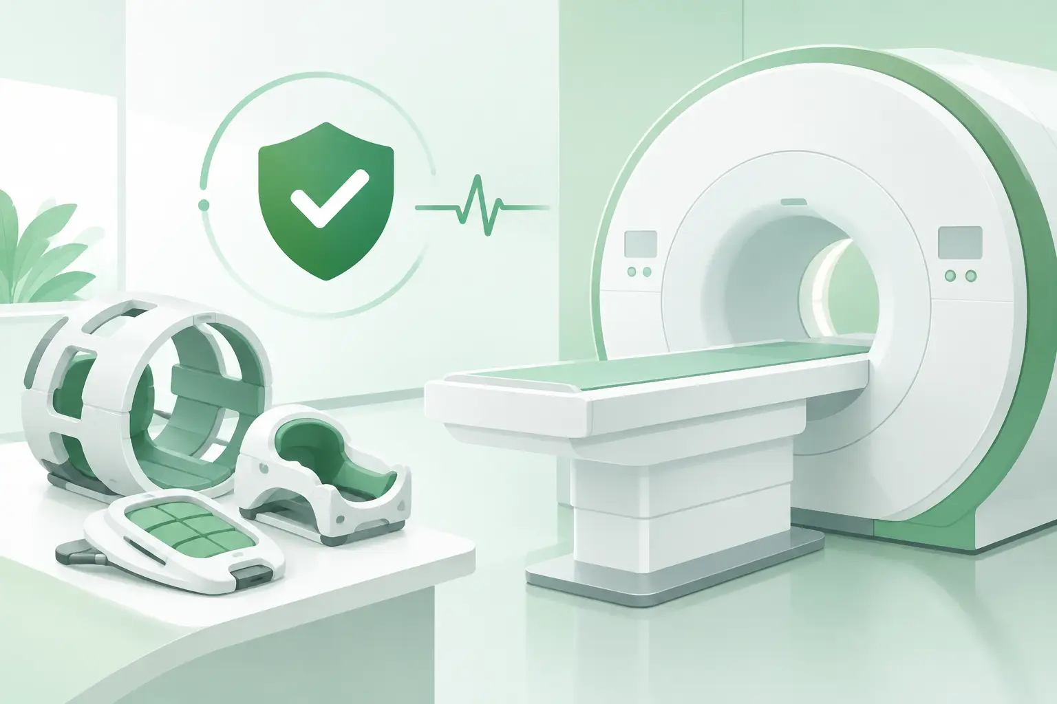
The integrated body coil typically provides broad coverage and, on many systems, transmission capability. Dedicated local coils provide higher signal closer to the anatomy. A head coil, knee coil, shoulder coil, wrist coil, spine array, or cardiac array is therefore not an interchangeable accessory. It is a system-specific signal-reception component with defined geometry, electronics, cabling, and software recognition requirements.
Modern phased-array coils combine multiple independent elements. The scanner selects or combines those channels to create broad coverage while preserving high local signal. This design supports parallel imaging and helps shorten certain acquisitions, but it also adds failure points. A single damaged element, failed preamplifier, broken cable conductor, or connector issue can reduce image quality or cause the system to reject the coil entirely.
Why MRI Coil Failures Create Immediate Downtime
Coils are exposed to repeated handling, patient loading, cleaning, storage, and cable movement. Unlike many enclosed components, they operate in a high-contact environment. Housing latches, patient pads, cable strain-relief points, connectors, and internal electronics all experience wear over time.
Common signs of trouble include an intermittent coil recognition error, a channel fault during coil check, unusually low signal-to-noise ratio, localized shading or dropout, excessive noise, or a scan protocol that will not load when a particular coil is connected. A visible crack or damaged cable is clear evidence, but many failures are internal and may only appear during system diagnostics or clinical scanning.
The same symptom can have more than one cause. A coil error may originate in the coil itself, but it may also involve a damaged extension cable, table-side interface, connector pins, receive chain, or software configuration. Replacing a coil before confirming the fault path can consume time and budget without resolving the underlying issue.
Physical Damage and Cable-Related Faults
Cable damage is one of the most frequent coil-related concerns. Repeated bending near strain-relief points can break internal conductors while leaving the outer jacket apparently intact. Connector damage may be caused by impacts, improper engagement, contamination, or bent contacts. Latches and housings can also fail after years of clinical use, even when electrical performance remains acceptable.
A coil that works only in certain positions should be treated as a potential cable or connector problem. Intermittent performance is especially disruptive because a coil may pass a quick check and fail once positioned on a patient or moved during the exam.
Electronic and Element Failures
Within a phased-array coil, individual receive elements, detuning circuits, preamplifiers, and control components must operate correctly. An element fault may create a visible region of low signal or noise, while a more significant electronics failure may prevent coil identification altogether.
Technicians should avoid judging a coil solely by whether the scanner recognizes it. Recognition confirms communication, not full image performance. A proper evaluation should include the manufacturer-recommended coil check and, where appropriate, phantom imaging that can reveal channel imbalance, signal loss, or artifact patterns.
A Practical MRI Coil Troubleshooting Sequence
Before sourcing a replacement, establish whether the coil is the confirmed failed component. Start by documenting the scanner model, software level if relevant, coil name displayed at the console, reported error code, and the precise conditions under which the issue occurs. This record is valuable when comparing a replacement option or discussing a repair path.
Next, inspect the coil housing, cable, strain relief, connector, pins, locks, and patient-contact surfaces. Check for cracks, fluid intrusion, loose sections, bent contacts, or evidence of pinching. Follow site safety procedures and manufacturer guidance before connecting or disconnecting any MRI component.
If the system and service documentation allow it, test with a known-good compatible coil and inspect any removable interface or extension cable. A known-good comparison helps separate a coil-specific problem from a scanner-side issue. Run the relevant coil diagnostics and review channel-level results rather than relying on a single pass/fail indication.
For image-quality complaints, obtain controlled phantom images using the affected coil and compare them with prior performance or a known-good unit. Look for localized signal loss, nonuniformity, noise bands, and artifacts that correlate with a particular element or cable position. The troubleshooting process should produce enough evidence to make a replacement decision with confidence.
Selecting the Right Replacement MRI Coil
Compatibility is more specific than OEM name and anatomy. A coil built for one Siemens, GE Healthcare, Philips, Canon/Toshiba, or other MRI platform may not operate on another system from the same manufacturer. Even similar-looking coils can differ in connector design, channel count, mechanical fit, patient table interface, software support, or revision level.
The most reliable starting point is the OEM part number from the coil label, service documentation, or existing asset records. Include the scanner model, coil description, serial number when available, connector photographs, and any assembly or revision number. A precise request reduces the risk of receiving a near-match that cannot be installed or recognized.
When evaluating used or refurbished MRI coils, ask about the coil’s condition, testing method, included cable or accessories, and whether the quoted component is the exact requested part number or a documented compatible substitute. A lower-cost coil that lacks the correct interface, has unverified channels, or arrives without a required component can extend downtime rather than reduce it.
There is also a practical trade-off between a direct replacement and a repair. Repair may be appropriate for a known cable, connector, housing, or electronic fault when the coil is serviceable and turnaround is acceptable. Replacement can be the better operational decision when a critical coil has sustained extensive damage, has recurring intermittent faults, or is needed quickly for a fully booked modality.
Procurement Details That Prevent Delays
MRI coil sourcing moves faster when the request contains technical evidence rather than a general description. “Need a head coil” is usually insufficient. A complete request should identify the OEM, scanner model, coil type, exact part number, revision where applicable, fault condition, quantity, and whether the site needs only the coil or associated hardware as well.
For legacy scanners, the part may be discontinued through standard channels while still available through the imaging aftermarket. This is where a supplier with part-number-level cross-referencing and access to multiple OEM environments can materially reduce search time. Meditegic supports this type of exact-match sourcing for MRI RF coils and other difficult-to-locate imaging components, including parts for established and legacy systems.
Before installation, verify that the received unit matches the requested part number and physical configuration. Retain packing documentation and perform acceptance checks according to the site’s procedures. For a coil supporting high-volume exams, it is also reasonable to assess whether a tested backup unit should be available, particularly when the installed system relies on a specialized anatomy coil that is difficult to source quickly.
MRI Coils Are Operational Components, Not Accessories
An MRI coil is part of the signal chain and a direct determinant of clinical workflow. Treating it as a generic accessory creates avoidable compatibility and performance risks. The correct approach is to isolate the fault, document the component accurately, verify part-number compatibility, and source a tested replacement aligned with the scanner’s configuration.
That level of discipline helps protect more than a single exam slot. It keeps a high-value imaging system available for the studies it was built to perform.