An MRI can be fully powered, pass basic console checks, and still be unavailable for scanning because a thermal fault has taken one cooling loop out of specification. MRI cooling system components protect several high-value assemblies with different heat loads, flow requirements, and fault tolerances. Treating the cooling system as one generic “chiller problem” can delay diagnosis and result in an incorrect replacement part.
For clinical engineering teams, ISOs, and imaging service providers, the practical objective is clear: identify which cooling circuit is affected, isolate the failed component, and source the exact compatible replacement before a temperature or flow fault becomes extended downtime.
Why MRI cooling architecture is not one system
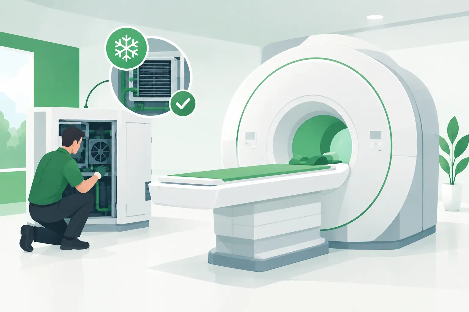
Most superconducting MRI platforms use more than one cooling function. The magnet cryostat has a refrigeration arrangement that supports the superconducting magnet and manages cryogenic heat load. Separate water-based cooling circuits may remove heat from gradient amplifiers, RF power equipment, cabinet electronics, or other high-power assemblies. Some installations also depend on facility water or a remote heat-rejection loop.
The exact arrangement varies by OEM, field strength, system generation, and site configuration. A legacy Siemens, GE, or Philips platform may use a different compressor, chiller control scheme, hose configuration, sensor set, or electrical interface than a newer system from the same manufacturer. A part that looks physically similar may not communicate correctly with the installed controller or meet the required flow and temperature range.
This distinction matters during triage. A magnet refrigeration alarm should not automatically lead to a search for a gradient chiller pump. Likewise, elevated gradient temperature after repeated scanning may point to poor heat rejection, restricted flow, or a failing circulation component rather than a gradient amplifier defect.
Core MRI cooling system components
Magnet refrigeration components
In superconducting MRI systems, the cryostat is designed to keep the magnet at cryogenic operating conditions. Depending on the magnet design, the refrigeration package can include a cold head, helium compressor, compressor drive electronics, helium lines, filters, pressure-related hardware, and associated sensors or interlocks.
The cold head transfers heat from the cryostat refrigeration stage, while the compressor circulates helium gas through the closed-loop refrigeration circuit. Degraded cold-head performance, compressor faults, contaminated helium circuits, line leaks, incorrect pressures, or failed control boards can all produce cooling alarms. These are specialized assemblies. Compatibility must be verified against the magnet model, installed refrigeration configuration, OEM part number, and revision level.
Cryogenic work also has a clear boundary: it requires qualified personnel and the proper procedures for the system. A cooling parts supplier can help identify and locate an exact-match assembly, but installation, helium handling, and magnet safety decisions belong with trained MRI service professionals.
Water chiller and heat-rejection assemblies
Water chillers are common in MRI environments because gradient amplifiers and related electronics generate substantial heat during scanning. A typical chiller package may include a compressor, condenser, evaporator or heat exchanger, circulation pump, reservoir, fan assemblies, flow switch, pressure switches, temperature sensors, controller board, contactors, relays, filters, fittings, and hoses.
Failure symptoms are not always dramatic. A chiller may start normally but show reduced flow after it warms up. A pump may be noisy, intermittent, or unable to maintain pressure. A fouled heat exchanger, weak fan motor, failing compressor, or unstable temperature sensor can cause recurring overtemperature faults under heavy sequence demand.
For replacement sourcing, the chiller nameplate alone is useful but often insufficient. The correct request should include the MRI make and model, chiller model, OEM and manufacturer part numbers, voltage and frequency, cooling capacity where available, plumbing connection details, and photos of labels and connectors. This prevents a mismatch between a mechanically similar unit and the actual installed system.
Pumps, valves, and fluid-path hardware
Circulation hardware is frequently overlooked because it is less visible than a complete chiller. Yet a failed pump, sticking valve, blocked strainer, leaking quick-disconnect, deteriorated hose, or damaged fitting can stop a cooling loop from meeting flow requirements.
Pumps must be matched by more than mounting dimensions. Flow rate, head pressure, motor voltage, connector type, fluid compatibility, seal material, inlet and outlet orientation, and control method can all affect suitability. In some designs, a pump is integrated into a chiller skid; in others, it is a separately replaceable service item.
Leaks require careful interpretation. A visible leak at a fitting may be the root cause, but it can also reveal system overpressure or a failed valve. Replacing only the hose or connector without checking pressure control and pump operation can lead to repeat failure shortly after the system returns to service.
Sensors, switches, and control electronics
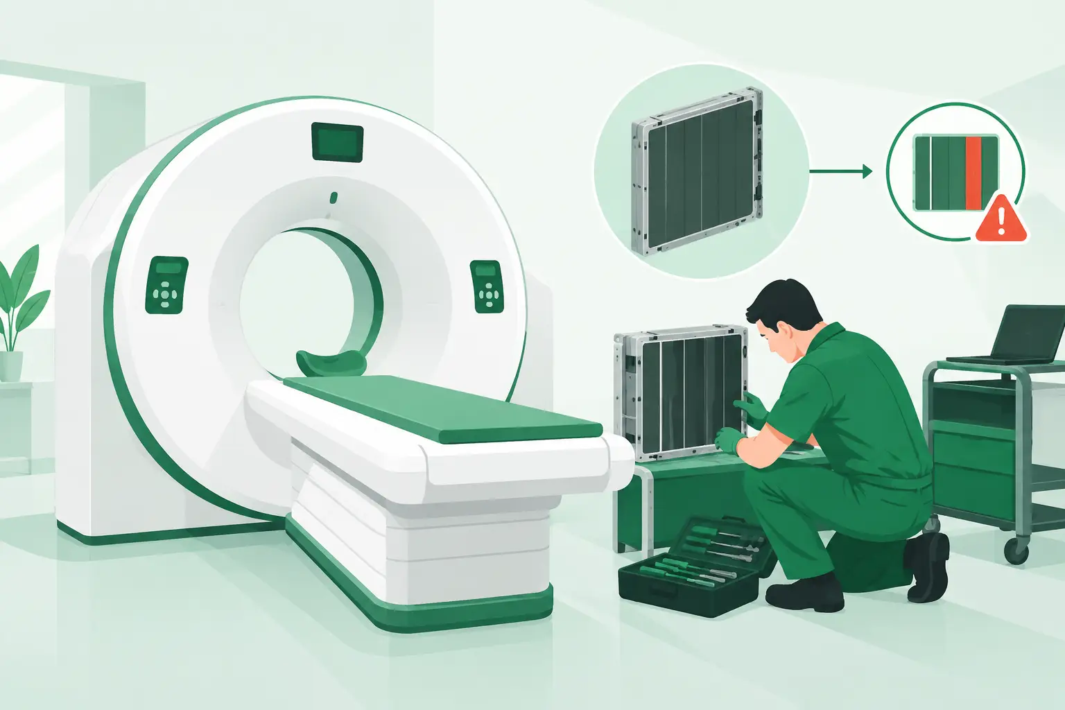
A cooling system relies on feedback. Temperature probes, flow sensors, pressure transducers, float switches, conductivity sensors, and interlock circuits provide the data that permits or inhibits scanning. When one of these devices drifts out of range or sends an intermittent signal, the system may report a cooling fault even when the mechanical equipment appears to operate.
Control boards and power components are equally consequential. A chiller controller may fail to energize a pump, fan, compressor contactor, or alarm relay. A relay with burned contacts can create an intermittent fault that resembles a motor or compressor issue. Before ordering a board, technicians should confirm the board identifier, firmware or revision markings when applicable, and every connector position.
Fans, filters, and electrical power parts
Cabinet and condenser airflow components can have a direct effect on cooling performance. Failed fan motors, worn bearings, cracked blades, clogged filters, and obstructed condenser fins reduce heat rejection. These faults may first appear only during extended scan blocks or warm ambient conditions.
Power supplies, contactors, overloads, capacitors, fuses, and wiring harnesses also belong in the diagnostic path. Replacing a compressor when the actual issue is a failed start component or control output adds cost and time. Conversely, repeatedly replacing electrical parts without measuring compressor condition can prolong downtime.
How to narrow the failure before ordering parts
Start with the system fault history and identify whether the alert is magnet-related, gradient-related, RF-related, or associated with an external chiller. Record operating temperatures, flow readings, pressures where the service procedure permits, ambient conditions, and the point at which the fault occurs. Does it occur at startup, after an hour of scanning, or only under high-duty sequences? That pattern has diagnostic value.
Then inspect the physical cooling path. Look for fan operation, pump noise, vibration, leaks, hose condition, blocked airflow, unusual compressor cycling, and evidence of overheated electrical components. Do not rely on one observation. A normal-running pump can still deliver inadequate flow, and a displayed temperature can be inaccurate if the sensor is drifting.
Finally, verify the failed item at the part-number level. The information that most improves sourcing accuracy is the OEM part number, manufacturer label, serial number where applicable, system model, and clear photographs of labels, connectors, and mounting interfaces. For boards, include both sides if revision markings or connector layouts differ. For pumps and valves, include the fluid connections and flow direction.
Replacement strategy for current and legacy MRI platforms
A complete chiller replacement can be appropriate when multiple major components are degraded, the unit has repeated refrigerant-side faults, or the original package is no longer supportable. In other cases, replacing the pump, controller, fan assembly, sensor, or valve is faster and less disruptive. The right decision depends on verified fault isolation, installed configuration, lead time, and the service team’s capability to commission the repaired loop.
Used and refurbished assemblies can be practical options for mature MRI platforms, particularly when OEM support is limited or an original component is discontinued. The key is not simply availability. It is confirmation that the replacement matches the required part number or approved cross-reference, revision, electrical specification, and physical interface. A lower-cost component that cannot be installed immediately is not a downtime solution.
Meditegic supports this process by locating exact-match imaging cooling parts across a global supplier network, including difficult-to-source chiller assemblies, pumps, control boards, sensors, fans, and magnet refrigeration-related components for major OEM environments. A precise request with part-number data allows the sourcing process to move faster and reduces avoidable compatibility questions.
When cooling uptime is at stake, the most useful next step is not a broad search for an “MRI chiller.” Capture the alarm context, identify the affected loop, and document the component’s exact identifiers. That preparation turns an urgent parts request into a serviceable repair plan.