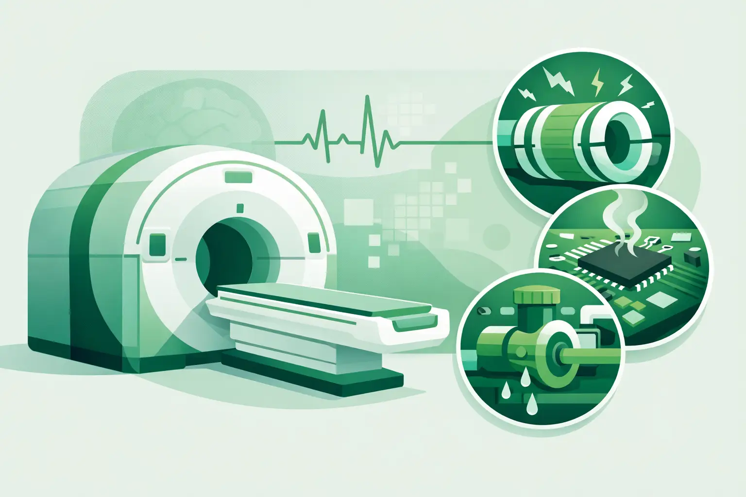
A gradient-related shutdown can take an otherwise functional MRI scanner out of service with little warning. The image may show distortion, the system may stop during initialization, or an interlock may prevent scanning entirely. MRI gradient components are central to spatial encoding, but they also operate under high electrical, thermal, and mechanical stress. For service teams, the priority is not simply identifying a “gradient fault.” It is isolating the affected assembly and securing the exact replacement configuration without extending downtime.
What MRI Gradient Components Do
MRI uses a powerful static magnetic field and RF energy to generate signal from the patient. Gradient fields add controlled, position-dependent changes to that magnetic field. They allow the system to select slices and determine where signal originates along the X, Y, and Z axes.
The gradient subsystem must switch current rapidly and precisely. A typical MRI gradient chain includes the gradient coil assembly, gradient amplifiers, power conversion hardware, control electronics, cooling circuits, filters, cables, connectors, and safety-monitoring elements. The exact architecture differs by OEM, magnet generation, field strength, and scanner platform. A Siemens system, GE platform, Philips installation, or legacy Toshiba/Canon MRI may use substantially different assemblies even when symptoms appear similar.
This is why generic descriptions such as “gradient board” or “X-axis amplifier” are not enough for procurement. The OEM part number, system model, serial or configuration details, and fault history matter. In many cases, a physically similar component is not electrically or firmware-compatible with the installed system.
Why Gradient Failures Have an Outsized Operational Impact
Gradient hardware is responsible for rapidly changing magnetic fields, which means it is exposed to repeated thermal cycling, vibration, high current, and demanding cooling requirements. A fault in one part of the chain can trigger system protection before the source of the issue is obvious.
For an imaging center or ISO, this can create a difficult service event. The scanner may be unable to complete calibration, fail a pre-scan check, display a gradient overtemperature warning, or produce artifacts that make clinical imaging unacceptable. In some cases, the error points to an amplifier or power supply while the underlying cause is a cable, cooling restriction, connector issue, or coil-related problem.
The trade-off is clear: replacing the first suspected module may restore operation quickly, but it can also create unnecessary cost and repeat downtime if diagnosis is incomplete. Conversely, extended troubleshooting can be impractical when a high-value MRI asset is idle. The best path depends on the fault evidence, system history, availability of qualified technical support, and whether a known-good exact-match spare can be sourced promptly.
Common MRI Gradient Component Failure Points
Gradient amplifiers and power electronics
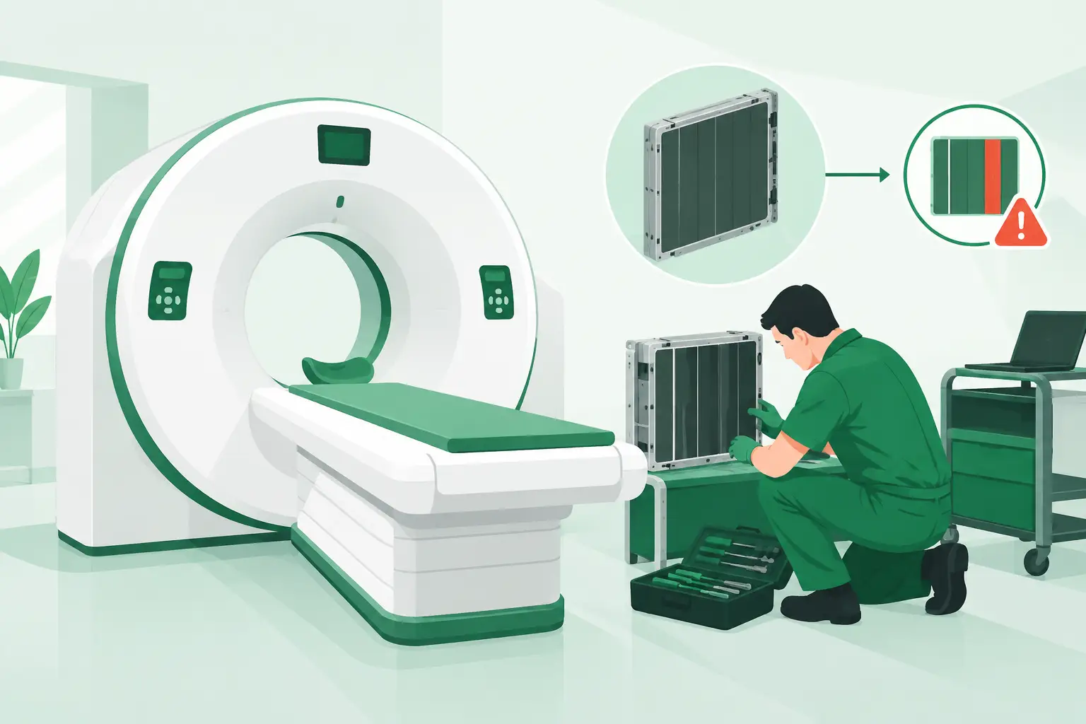
Gradient amplifiers drive high-current waveforms to the coil assembly. These units can fail because of component aging, cooling problems, internal power-stage faults, control-board issues, or repeated overload events. Symptoms may include axis-specific errors, amplifier communication faults, inability to initialize gradients, or scanner shutdown during demanding sequences.
An amplifier fault code does not always prove that the amplifier is defective. Technicians should consider incoming power quality, cabinet cooling, interconnects, controller communication, and the load presented by the gradient coil. However, when diagnostics and substitution testing confirm the amplifier, part-number-level replacement is essential. Revisions, connector layouts, control interfaces, and software compatibility can differ within the same product family.
Gradient coil assemblies
The gradient coil assembly sits within the magnet bore and is one of the most consequential and complex items in the subsystem. It contains conductors configured for the three gradient axes and may include integrated cooling paths and associated monitoring components.
Possible coil-related issues include open or shorted circuits, insulation breakdown, cooling leaks or restrictions, and mechanical damage. Acoustic noise is normal during scanning, but an unusual change in sound, vibration, or image distortion may warrant investigation. A gradient coil issue can also present indirectly through amplifier overload or protection faults.
Replacement decisions for coil assemblies require particular care. Compatibility extends beyond the model name. Bore geometry, magnet configuration, patient table integration, installed software, cable routing, and OEM revision details may affect fit and operation. These are not parts to source from a broad description or a photograph alone.
Cooling components and thermal protection
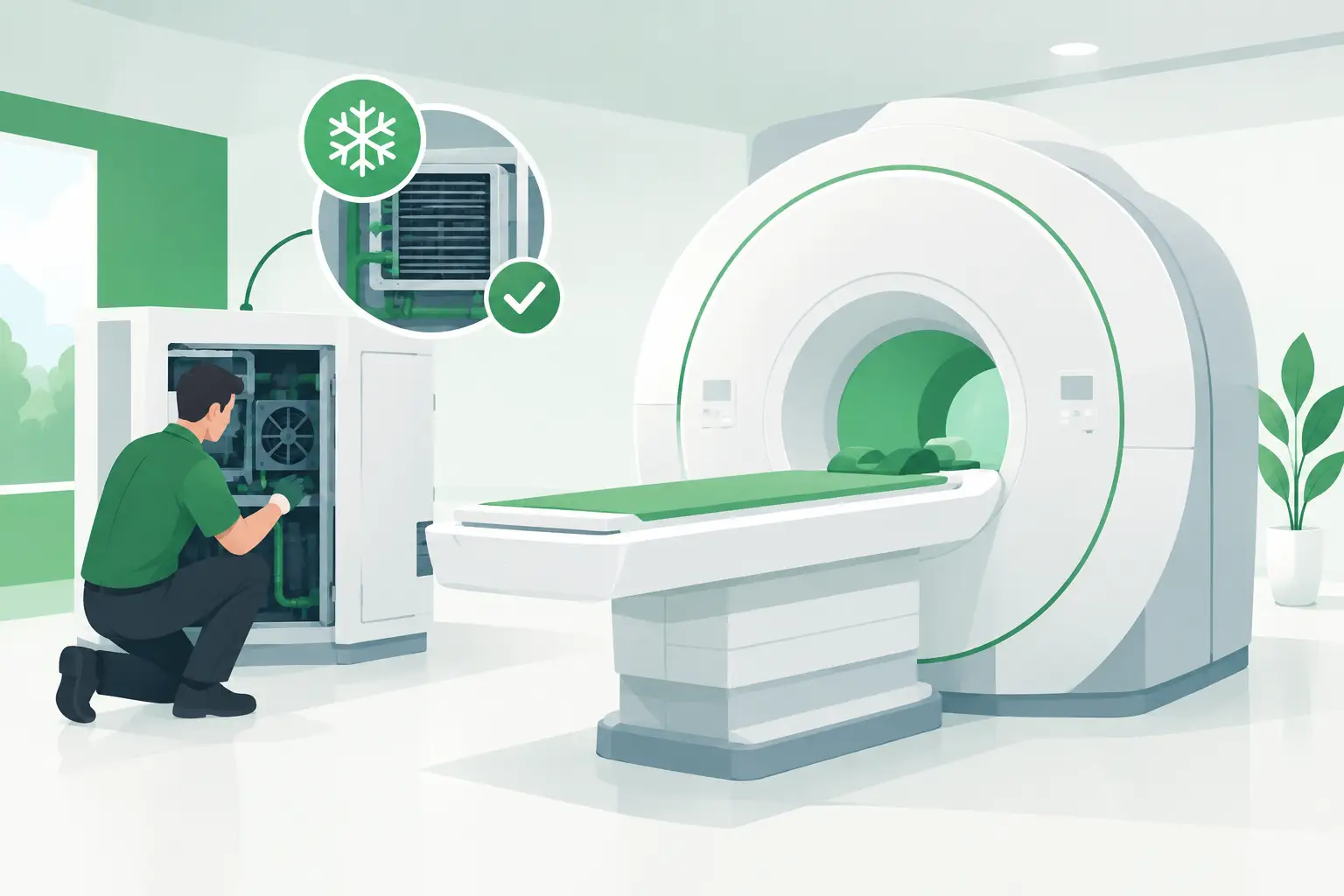
Heat management is fundamental to gradient reliability. Depending on the system, the gradient subsystem may use water cooling, chilled-water interfaces, heat exchangers, pumps, hoses, flow sensors, temperature sensors, fans, or cabinet-level cooling components. Reduced flow, poor heat transfer, contamination, a failed pump, or a sensor fault can lead to overtemperature alarms and protective shutdowns.
Cooling-related diagnosis should include more than a visual inspection. Compare operating temperatures and flow readings against the system’s service documentation where available. Check for leaks, hose condition, blocked filters or heat exchangers, pump performance, and evidence of prior thermal events. Replacing an amplifier without correcting inadequate cooling can shorten the life of the replacement component.
Cables, connectors, and control boards
High-current cables and signal connections are easy to overlook because they may not be the most expensive items in the gradient chain. Yet damaged insulation, loose connections, corrosion, pin damage, or intermittent communication can produce faults that resemble a major hardware failure. Control boards, interface boards, and monitoring electronics can similarly prevent a functioning amplifier from operating correctly.
These components deserve focused inspection during diagnosis, especially after transport, installation work, a coolant incident, or prior service activity. When replacing a board or cable set, confirm connector type, cable length, revision level, and mating components. A near-match can introduce new errors or safety issues.
A Practical Process for Identifying the Right Spare
A productive sourcing request starts with technical identification, not a broad equipment description. Record the MRI manufacturer, system model, magnet type or field strength if relevant, and the OEM part number from the failed assembly label. Include the component revision, serial number, observed fault code, and whether the part is an amplifier, coil-related item, PCB, power module, cable, or cooling component.
Photographs of labels and connectors can help resolve ambiguous descriptions, but they should support the part number rather than replace it. For legacy systems, prior service records and removed-part labels are often valuable because documentation may no longer be readily available at the site.
Before ordering, verify whether the replacement must match a specific revision and whether programming, calibration, configuration, or qualified installation is required. A refurbished component may be an appropriate option when it has been correctly identified and evaluated for the intended application. The right choice depends on urgency, lifecycle strategy, service capability, and the condition of the available part.
For difficult-to-source MRI gradient components, Meditegic supports technical buyers by sourcing against OEM part numbers across major imaging brands and legacy platforms. That approach reduces the risk of spending time on components that are merely similar rather than correct for the installed system.
When a Fault Is Not Really a Gradient-Part Failure
Not every gradient error originates in a replaceable gradient component. System software, cabinet power issues, environmental temperature, chiller performance, RF-related interactions, and scanner configuration can all affect the way a fault presents. A recurring error after replacement is a signal to revisit the broader system condition rather than assume the newly installed part has failed.
This is especially relevant after a scanner has been relocated, restarted after prolonged downtime, or returned to service following major maintenance. Changes in facility cooling, electrical supply, grounding, or equipment-room conditions can expose weaknesses that were previously intermittent.
A disciplined record of error codes, scan conditions, temperatures, replaced parts, and test outcomes makes future service faster. It also gives the sourcing team the information needed to identify an exact-match spare without back-and-forth delays.
Protecting Uptime in an Aging MRI Fleet
As MRI platforms age, gradient electronics, cooling hardware, and OEM-specific assemblies can become harder to obtain through standard channels. Keeping accurate part records for high-risk modules is often more valuable than maintaining a large, unfocused spare inventory. The goal is to know what is installed, what has failed before, and which components have long lead times.
When an MRI gradient issue occurs, treat the part number as a technical requirement, not an administrative detail. Accurate identification, complete fault information, and a verified compatibility check give service teams the best chance of returning the scanner to productive use with one well-supported replacement decision.