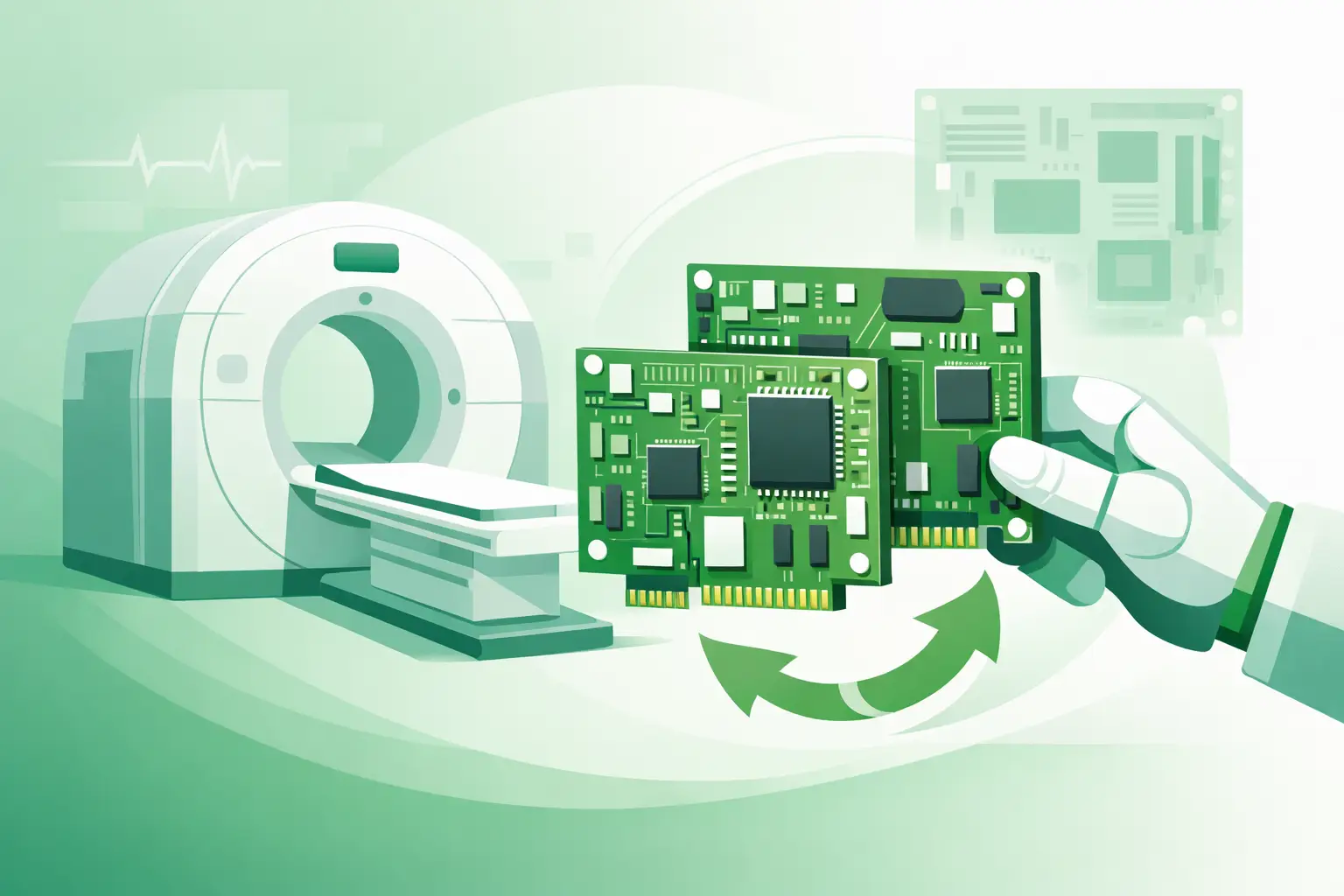
A CT system can be down because of a board no larger than a laptop. When a gantry control, acquisition, power-distribution, table-control, or communication board fails, the immediate challenge is rarely finding a board that looks similar. Philips CT boards must be matched to the installed system, OEM part number, revision, and functional role. A visually similar PCB with the wrong firmware compatibility or connector configuration can extend downtime rather than resolve it.
For clinical engineering teams, ISOs, and imaging service companies, the practical objective is clear: confirm the fault, preserve the identifiers on the removed assembly, and source an exact-match replacement before a difficult repair becomes a prolonged outage. This is especially relevant for legacy Philips platforms where OEM availability may be limited and board-level inventory is fragmented across multiple regions.
Why Philips CT boards require more than a visual match
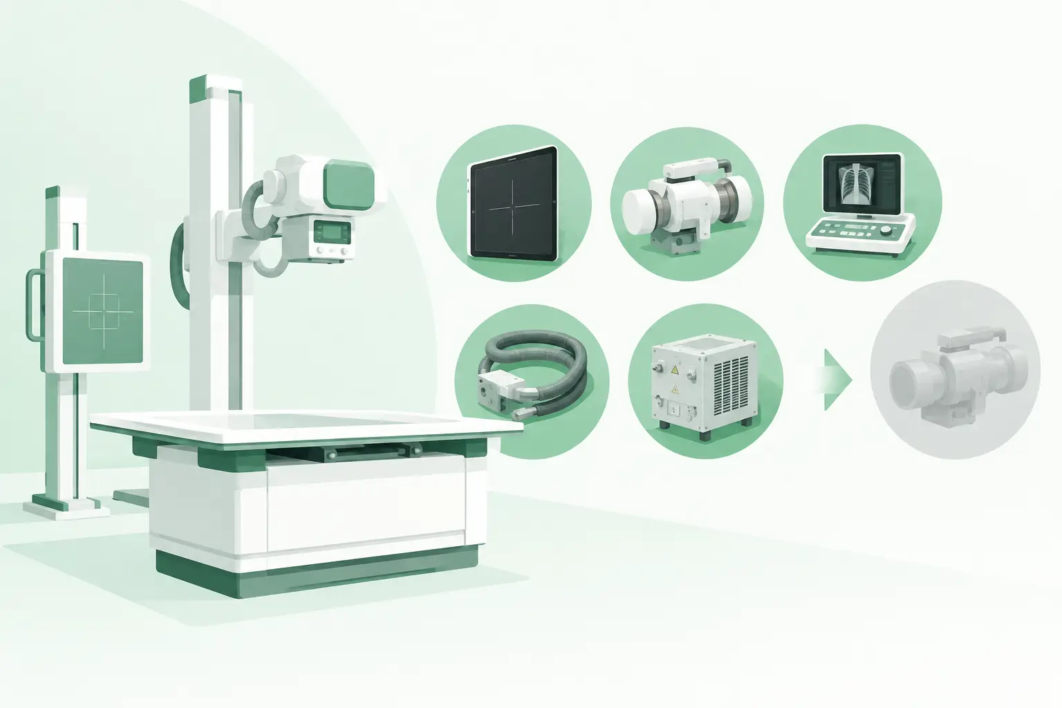
A CT system contains multiple electronic assemblies that coordinate motion, X-ray generation, detector data acquisition, image reconstruction, cooling, safety interlocks, patient table movement, and operator-console communication. Some boards are mounted in the gantry, while others are located in cabinets, power-distribution areas, detector electronics, or console assemblies. Their function is specific to the system architecture.
Two assemblies can share a board layout, enclosure, or connector style while carrying different part numbers, revisions, programmable components, or installed options. In some cases, a replacement board may physically fit but fail to communicate with the system, generate an initialization error, or produce intermittent faults under scan load. That is why the printed OEM number on the board, label, or module is more useful than a broad description such as Philips CT control board.
Revision control also matters. Later revisions may supersede earlier assemblies, but a valid supersession should be confirmed against the scanner configuration. An undocumented substitution can create problems with software level, detector configuration, power requirements, or peripheral interfaces. Exact matching is not administrative detail. It is part of the technical repair process.
Identifying the correct Philips CT board
The best time to collect identification data is before the failed part leaves the site. Photograph the assembly in place, including cable routing and connector positions, then record every label and marking. A single number copied incorrectly can lead to an unusable quote or the wrong shipment.
Record the system and board identifiers
Start with the CT system model and the available system identification information. Then capture the board or module part number exactly as shown, including prefixes, suffixes, dashes, and revision letters. Also record serial numbers, barcode labels, PCB markings, and any secondary labels on shielding or attached modules.
The assembly location provides useful context. For example, a board removed from a gantry control cabinet should not be described simply as a console PCB. State whether it is associated with detector electronics, the table, generator interface, motion control, power supply control, cooling, or another subsystem. Clear location data helps a sourcing specialist distinguish between similar assemblies used elsewhere in the platform.
Photographs should show both sides of the board when practical, as well as all connectors, daughterboards, heat sinks, and attached cables. Do not remove labels or discard the original packaging until the replacement has been inspected and accepted.
Include the failure information
A part number identifies what to source. Fault information helps determine whether the board is actually the source of the problem. Provide the error code, symptom, fault frequency, conditions under which it occurs, and any test results already completed. Note whether the failure is constant, intermittent, scan-load dependent, temperature related, or linked to a particular motion or detector event.
This information can prevent a common and expensive mistake: replacing an electronic board when the root cause is a power rail, cable harness, connector, cooling issue, interlock, grounding fault, or corrupted configuration. A board may be the correct suspect after isolation testing, but it should not be treated as the default cause simply because an error message references that subsystem.
Confirm the diagnosis before ordering
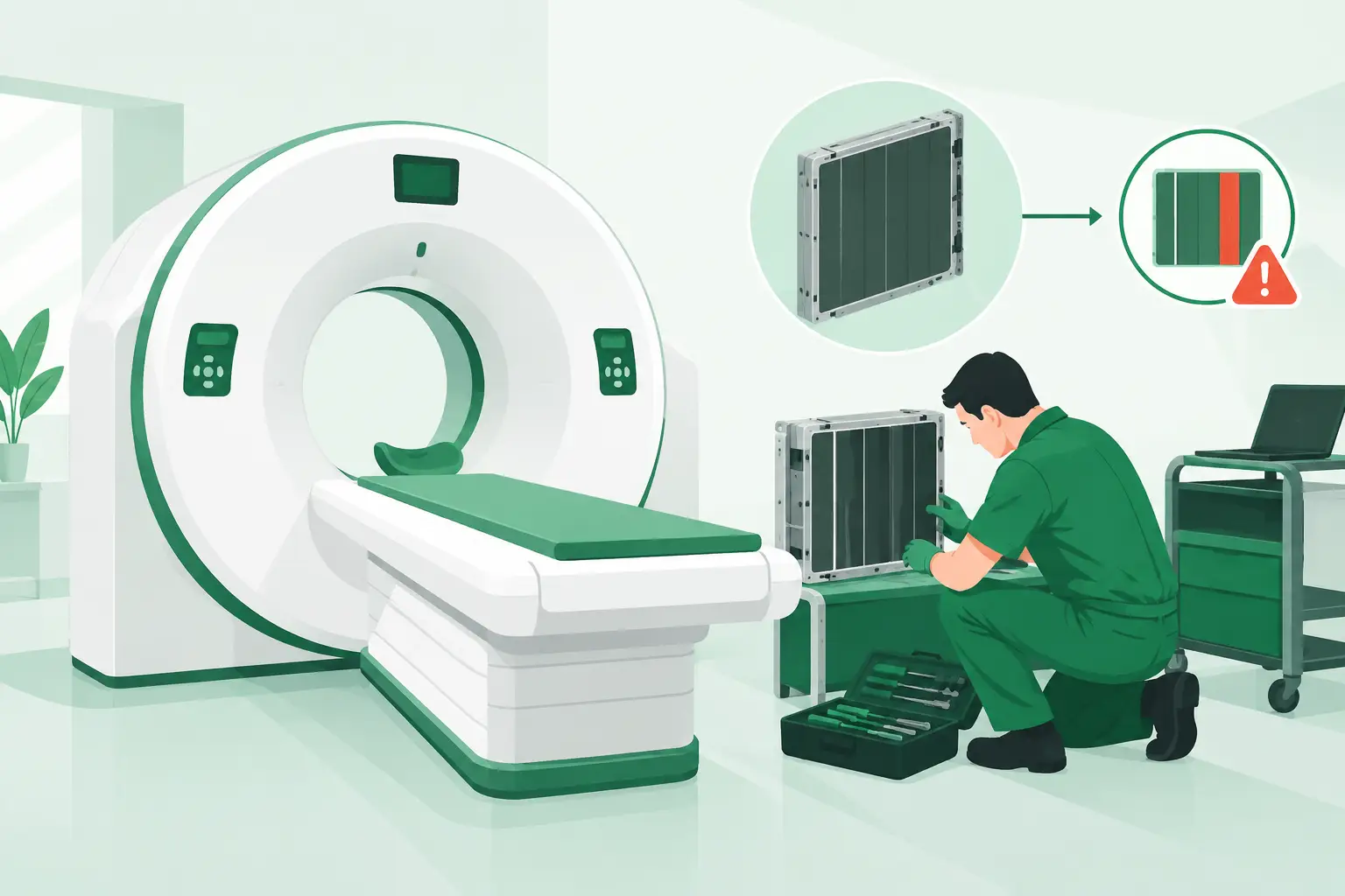
Board replacement is most effective when it follows a structured fault isolation process. Review system logs and service documentation, verify incoming and local power conditions, inspect connectors for damage or contamination, and check for signs of overheated components, corrosion, liquid exposure, or loose mounting hardware.
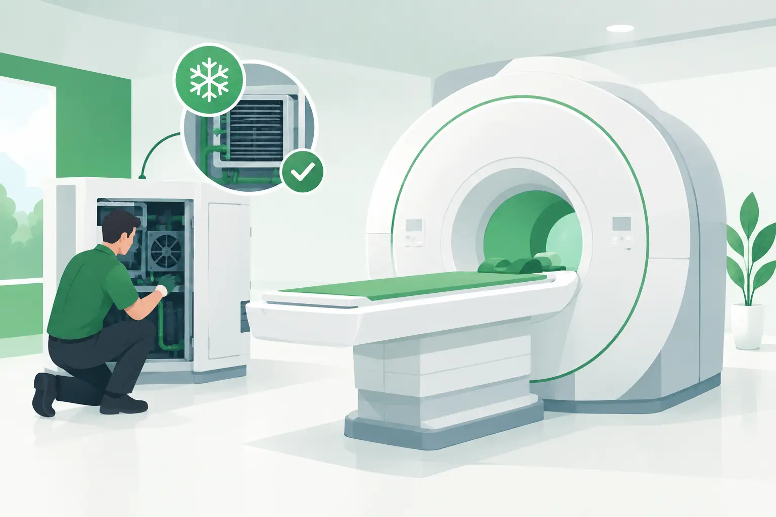
Intermittent behavior deserves particular caution. A gantry board that faults only after extended operation may be affected by thermal stress, cooling performance, a marginal power supply, or a connector that changes resistance with vibration or temperature. Swapping a board without checking those upstream conditions may produce a temporary recovery followed by another failure.
Where service procedures permit, compare measured voltages, communication status, or known-good module behavior. Follow applicable Philips service documentation and site safety procedures. CT equipment includes high-voltage, moving, and radiation-producing subsystems. Board-level work should be performed only by qualified personnel with the appropriate system knowledge, lockout practices, and post-repair verification process.
It also helps to determine whether the failed assembly needs a programmed configuration, calibration procedure, software installation, or system-level acceptance test after replacement. A replacement part can be electrically correct yet still require configuration steps before the scanner returns to clinical operation.
Sourcing Philips CT boards with fewer delays
Once the need is confirmed, the quality of the request directly affects turnaround. A useful sourcing request includes the system model, exact OEM part number, revision, serial number when available, board location, fault description, photographs, required quantity, and delivery urgency. This enables suppliers to search part-number-level inventory rather than making assumptions from a general board description.
Condition should be discussed in operational terms. Used parts may be appropriate when the exact assembly is scarce and the source can verify identification and condition. Refurbished assemblies can be a better fit when repair, testing, or replacement of known failure points has been performed by a qualified provider. Select new-old-stock inventory may be available for certain items, but age, storage conditions, and compatibility still need review.
The right choice depends on the board's criticality, the installed system's remaining service life, site risk tolerance, and the availability of a backup part. For a high-impact failure on a legacy scanner, an exact used or refurbished match available promptly may be more valuable than waiting for an uncertain alternative. For a recurring failure, it may be wise to investigate the underlying environmental or power condition before installing another assembly.
Meditegic supports this process by sourcing diagnostic imaging spare parts at the OEM part-number level across Philips and other major imaging platforms. For hard-to-find CT electronics, detailed identification data improves the speed and accuracy of the search.
Inspection and installation are part of the repair
Before installation, compare the delivered part against the purchase requirement and the removed assembly. Confirm the OEM part number, revision, connector count and placement, daughterboards, physical condition, and any included accessories. Check for shipping damage before the part is brought into the system.
Use appropriate electrostatic-discharge precautions. Confirm that jumpers, switches, or removable modules match the required configuration, and avoid transferring components from the failed board unless the service procedure specifically calls for it. Reconnect cables carefully and verify retention hardware, grounding straps, shielding, and cooling paths.
After installation, perform the required initialization, calibration, and functional checks. The scope will depend on the board's role. A table-related board may require motion and limit verification, while detector or acquisition electronics may require system diagnostics and image-quality checks. Record the replacement part number, serial number, installation date, system hours if available, fault code, and outcome in the service history.
Build a practical strategy for legacy CT electronics
A board failure is also useful inventory intelligence. If a specific Philips CT board is difficult to locate, document it as a risk item for the installed fleet. Maintain accurate part-number records for critical assemblies and identify which boards have no easy substitute. For systems with long lead times or constrained global availability, keeping an approved spare may be justified by the cost of a single extended outage.
The most effective replacement decision begins with precise evidence: the correct part number, the correct revision, a confirmed failure path, and a supplier that understands imaging-system components. That discipline gives technical teams a better chance of returning the scanner to service with the right board on the first attempt.