An MRI system can remain operationally available while its cold head is losing performance, then reach a threshold where magnet cooling alarms escalate into a forced shutdown. To troubleshoot MRI cold head faults effectively, service teams need to separate a true cold head or compressor problem from a helium circuit, cooling-water, power, or controls issue. Replacing the wrong component wastes critical uptime and can introduce avoidable risk around a superconducting magnet.
Start with the alarm history, not the replacement part
A cold head fault should be treated as a system-level diagnostic event. Review the exact error codes, alarm timestamps, operating mode, magnet pressure trend, cold-head temperature data where available, and recent service history. A single “cold head” message can reflect a thermal protection event, abnormal compressor operation, inadequate water cooling, a disconnected control signal, or an actual cryocooler failure.
Establish whether the issue is intermittent or persistent. An alarm that occurs only during high ambient temperatures, after long scan schedules, or when the chiller load rises points toward heat rejection or facility cooling. A fault that returns immediately after a reset, with normal utilities confirmed, is more consistent with a component, cable, controller, or compressor-related problem.
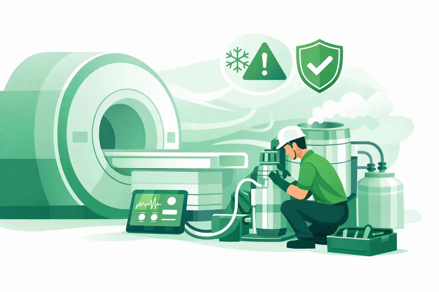
Before work begins, follow the applicable OEM service documentation and site safety procedures. MRI cryogenic assemblies involve high voltage, pressurized helium, moving mechanical equipment, and a high-field magnet environment. Cold head removal, helium circuit work, and recovery procedures should be performed only by personnel qualified for that specific system and procedure.
Verify the support systems around the cold head
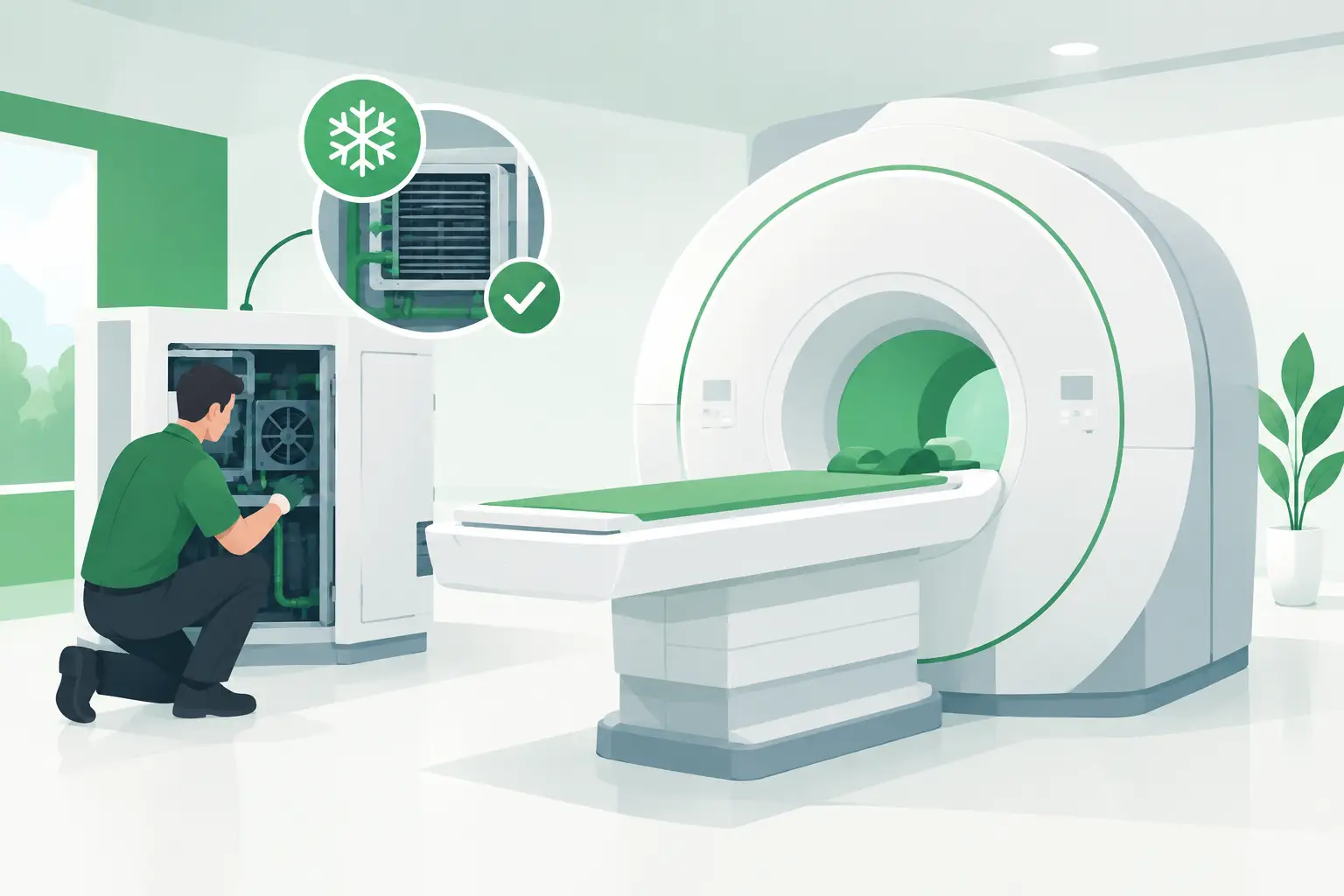
The cold head does not operate independently. Its cooling performance depends on the compressor, helium lines, water or air cooling arrangement, electrical supply, and control interface. Verifying these basics first prevents an expensive and unnecessary cold head exchange.
Check compressor operation and electrical conditions
Confirm that the compressor is receiving the specified voltage and that phase, grounding, breakers, contactors, and disconnects are within the system’s requirements. Inspect for tripped protection devices, loose terminations, heat damage, or abnormal noise during startup. A compressor that does not start reliably, cycles off under load, or shows an active fault requires diagnosis before the cold head itself can be judged.
Record operating current, pressure indications, and fault LEDs or display messages according to the OEM procedure. Do not use generic pressure targets across MRI platforms. GE Healthcare, Siemens Healthineers, Philips, and other OEM designs can use different compressor and control arrangements, and service values must be evaluated against the correct model documentation.
Confirm cooling-water flow and temperature
In water-cooled configurations, insufficient flow is a frequent cause of elevated compressor temperature and reduced cold-head performance. Check the facility water supply or chiller status, inlet and outlet temperatures, flow indication, filters, strainers, hoses, quick-connect fittings, and any external cooling alarms.
A partially blocked strainer or a chiller operating near its capacity may allow the system to run for a period before it overheats. That pattern can be mistaken for a failing cold head. Air-cooled installations require similar attention to room temperature, condenser cleanliness, fan operation, and clearance around the equipment.
Inspect helium lines and connections
Look for damaged, kinked, crushed, or improperly connected helium hoses between the compressor and cold head. Inspect quick-connects for contamination, damaged seals, incomplete engagement, or signs of leakage. A line restriction or poor connection affects the refrigeration cycle even when the cold head and compressor are otherwise functional.
Do not disconnect helium lines casually to “test” the system. Loss of helium charge, contamination, or incorrect reconnection can create a more serious service event. Use approved procedures and tools for the installed system.
Determine whether the cold head is actually underperforming
Once power, cooling, compressor function, and connections have been verified, assess whether the cold head is producing the expected thermal performance. The relevant evidence varies by platform, but may include cold-head temperature trends, shield temperature, helium vessel pressure behavior, compressor run time, and the time required to recover after a known operating condition.
A degrading cold head often produces a recognizable trend rather than an immediate hard failure. The system may show longer cool-down periods, repeated temperature warnings, a higher compressor duty cycle, or alarms that become more frequent over weeks. A sudden fault, by contrast, can result from a control cable, sensor, power supply, board, or compressor protection issue.
Compare current readings with prior service records whenever possible. Baseline data from earlier preventive maintenance is far more useful than judging a measurement in isolation. If no history exists, document all observed values before replacing components so post-repair performance can be verified objectively.
Inspect controls, sensors, and interlocks
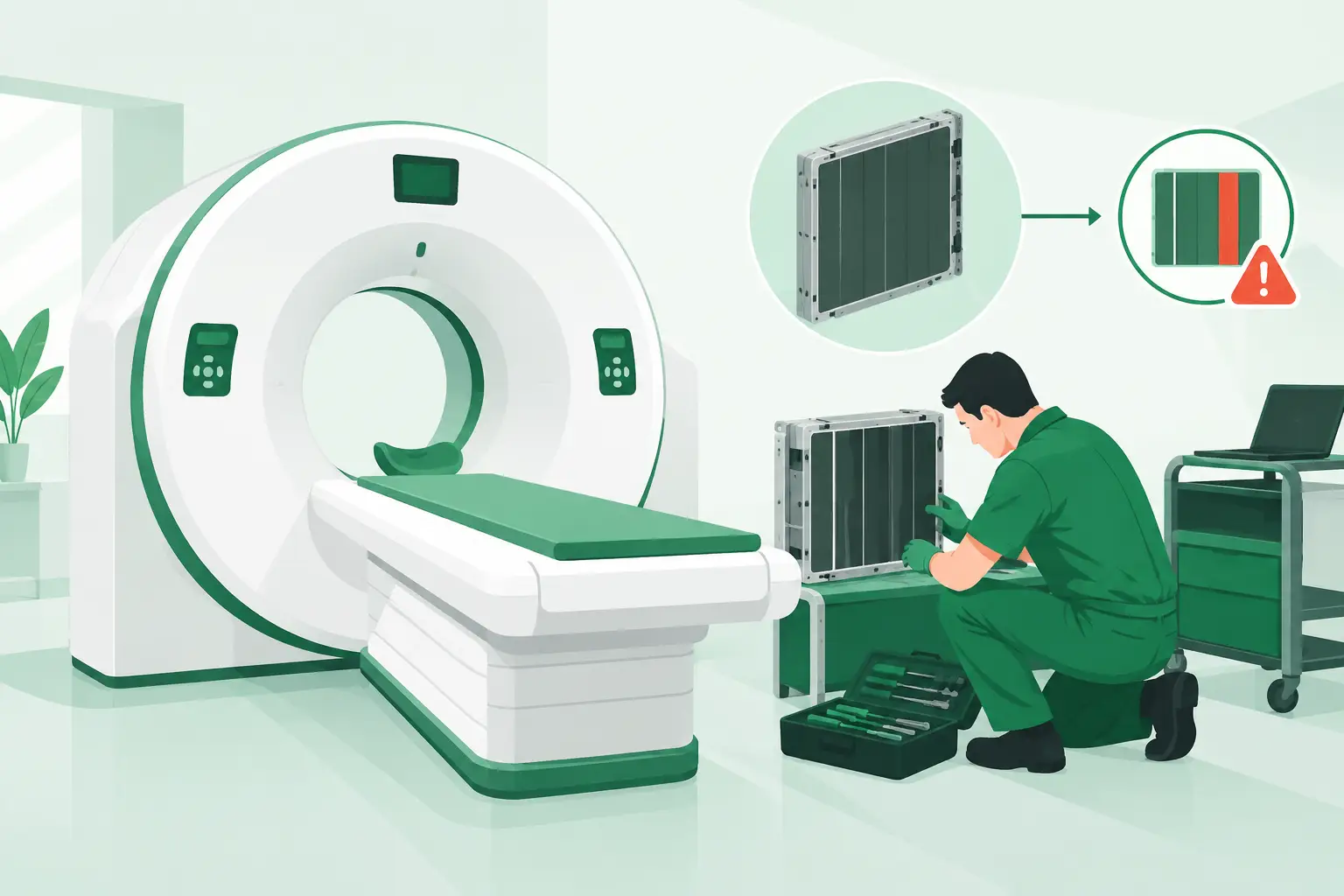
The cold head assembly is often blamed when the control system is reporting an implausible or missing signal. Inspect associated cables, connectors, harness routing, and controller interfaces for corrosion, pin damage, loose locks, moisture exposure, or mechanical stress. Verify sensor continuity and signal values only as specified in the OEM documentation.
Interlocks also matter. A compressor may stop because of coolant flow, temperature, pressure, emergency-stop, or cabinet safety conditions that are external to the cold head. Repeated resets without identifying the initiating interlock can increase downtime and may obscure the original fault pattern in system logs.
If a board-level issue is suspected, capture the full board part number, revision, and system configuration before sourcing. Similar-looking control boards can differ in firmware compatibility, connector arrangement, or supported compressor generation.
Know when replacement is the justified next step
Cold head replacement becomes the logical corrective action when utility conditions are within specification, the compressor and controls have been confirmed, helium connections are sound, and performance evidence indicates loss of refrigeration capacity. It may also be appropriate when the installed cold head has a documented failure mode or has reached the service-life pattern known for that system family.
The decision is not always binary. In some cases, a compressor overhaul, helium circuit service, sensor replacement, or cooling-system repair resolves the issue. In others, continuing to operate with declining cold-head performance raises the risk of an unplanned outage. The right choice depends on measured performance, equipment age, site scan volume, service capability, and the availability of a verified replacement.
Source the replacement by exact configuration
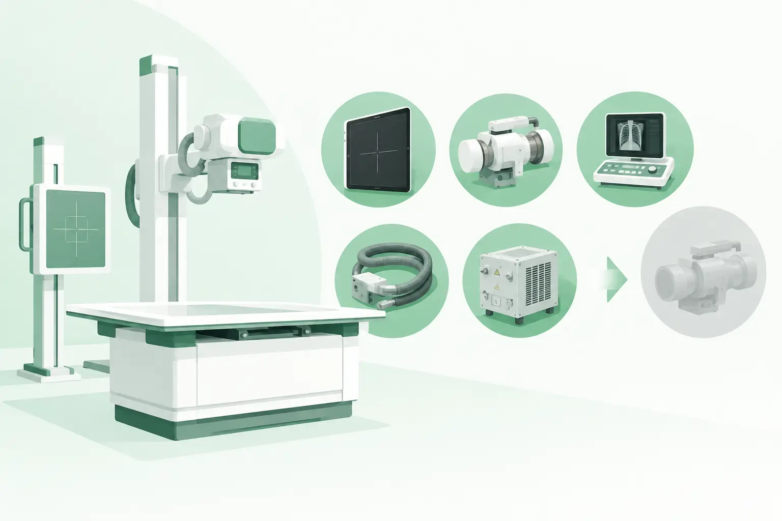
MRI cold heads are not interchangeable simply because the physical envelope or manufacturer name appears similar. Sourcing should begin with the OEM part number from the failed assembly, then confirm any revision code, serial-range applicability, connector type, compressor compatibility, magnet model, and included hardware. A complete parts request should also identify the MRI make, model, installed compressor, current fault description, and whether the need is for a cold head, compressor component, cable, controller, or cooling accessory.
For legacy MRI platforms, the original part may be discontinued or difficult to locate through standard channels. A specialized imaging-parts supplier can help cross-reference the exact assembly and determine whether a tested used, refurbished, or select new replacement is appropriate for the application. Meditegic supports this type of part-number-level sourcing across major OEM imaging environments, helping service teams avoid delays caused by incomplete identification.
When evaluating an available unit, ask what is included. A cold head may be offered as an assembly only, while another listing may include a cable set, fittings, sensor hardware, or related accessories. Confirm condition, test status, warranty terms, lead time, packaging requirements, and return handling before authorizing shipment. These details are especially relevant when the part is traveling internationally or serving a remote facility where a second delivery can add days to downtime.
Verify the repair after installation
A successful installation is more than clearing an alarm. After the approved replacement procedure is completed, confirm system initialization, compressor operation, cooling-water performance, cold-head temperature response, and the absence of recurring fault codes. Monitor the system through a sufficient operating period to ensure the original alarm pattern does not return under normal load.
Update the service record with the removed part number, replacement part number, serial number where applicable, observed measurements, fault codes, installation date, and post-repair results. That documentation shortens the next diagnostic cycle and provides a usable baseline if cooling performance changes again.
When a cold-head alarm appears, the fastest path back to service is disciplined isolation: verify the utilities and controls, document the performance evidence, and source only the exact component the diagnosis supports.