A linear dropout that follows one probe from room to room is not a scanning-technique issue. A bright vertical band that remains on every transducer may not be a probe issue at all. Effective ultrasound artifact troubleshooting starts by separating image behavior caused by physics and settings from evidence of a failing transducer, cable assembly, connector, or console channel. That distinction prevents unnecessary parts replacement and shortens time to resolution.
For clinical engineering teams, ISOs, and ultrasound service professionals, the goal is not simply to make an artifact disappear. It is to identify the failed level of the system with enough confidence to return the unit to service safely and source the exact replacement component if needed.
Start With a Controlled Baseline
Do not begin diagnosis with a patient study or a single stored image. Connect the suspect probe, select its correct preset, and scan a tissue-mimicking phantom when available. A uniform fluid-filled target can still help identify broad failures, but a phantom provides a more repeatable reference for penetration, uniformity, geometric accuracy, and dead elements.
Record the system model, software version, transducer model, probe serial number, active preset, and the exact location of the artifact on the display. Capture images at more than one depth, frequency, focal-zone position, and gain setting. The question is whether the defect stays fixed relative to the image, moves with a changed setting, or changes when the probe is exchanged.
Before opening covers or ordering parts, verify simple variables: correct exam preset, appropriate frequency range, overall and time-gain compensation settings, harmonic imaging state, compound imaging state, and output power. These controls can alter the appearance of legitimate artifacts substantially. They rarely create a clean, repeatable dead stripe in the same lateral position across routine settings.
Distinguish Expected Artifacts From Equipment Faults
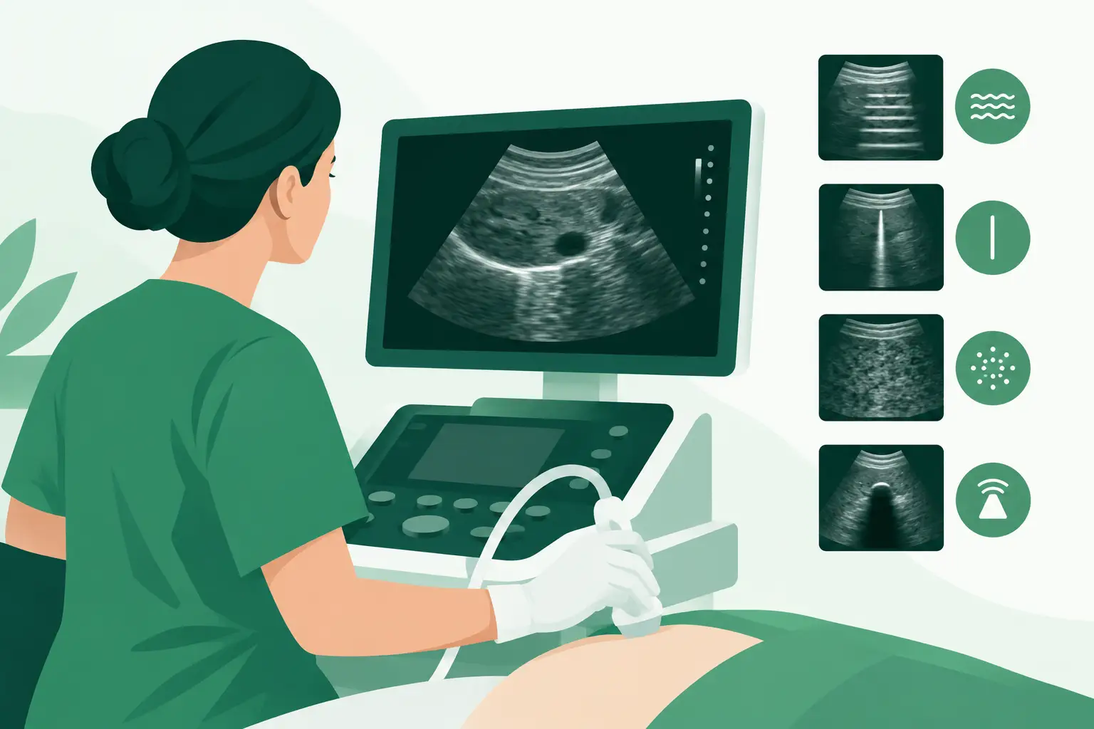
Many ultrasound artifacts are normal consequences of sound propagation. Reverberation, posterior acoustic shadowing, enhancement, mirror images, side-lobe effects, and refraction are meaningful only in their anatomic context. Changing probe angle, patient position, depth, or scanning plane usually changes their appearance. A true hardware-related artifact tends to be repeatable, independent of anatomy, and fixed in relation to the transducer footprint or screen geometry.
Probe-Related Patterns
A vertical dark band in a linear-array image, especially one extending through the field at a consistent lateral location, is a classic sign of failed or weak elements. It may reflect damaged piezoelectric elements, a fractured flex circuit, degraded matching layers, water ingress, or intermittent conductors near the strain relief. On a curvilinear or phased-array probe, element failure may appear as a wedge-shaped dropout, reduced sector uniformity, or localized loss of sensitivity.
Do not assume every dropout is permanent. Manipulate the cable gently near the connector, handle, and strain-relief areas while scanning a phantom. If the artifact appears, disappears, or shifts with cable position, suspect an intermittent conductor or connector issue. Avoid aggressive bending. It can worsen internal damage and create a misleading result.
Surface damage also matters. Cracked lens material, delamination, swelling, discoloration, or evidence of fluid intrusion should trigger removal from clinical use under the facility's probe inspection process. A probe can continue producing an image while presenting unacceptable electrical-safety, infection-control, or image-quality risk.
Console-Related Patterns
If multiple known-good probes show the same fixed artifact, attention shifts to the console. Common possibilities include a failed transmit or receive channel, connector-pin damage, probe-port board faults, beamformer issues, power-supply instability, or a software configuration problem.
A console fault often reveals itself through comparison. Test the suspect probe in a known-good compatible system, then test a known-good probe in the suspect system. If the defect remains with the probe, the probe is the likely source. If it remains with one console port regardless of the probe used, inspect the port and its associated electronics. If the problem occurs across all ports, investigate the shared signal path, power rails, image-processing hardware, and current software state.
This cross-test is one of the highest-value steps in ultrasound artifact troubleshooting. It replaces assumption with isolation. It also protects against ordering a replacement transducer when the actual failure is on a board or connector assembly.
Use the Artifact Location as a Diagnostic Clue
Artifact location is often more useful than its severity. A lateral defect that remains tied to the same array position points toward individual elements or their channels. A defect that starts at a fixed depth can indicate a processing or acquisition issue, although near-field reverberation and superficial acoustic conditions must be ruled out first.
Uniform loss of penetration across the entire image may result from incorrect frequency selection, excessive attenuation in the acoustic path, degraded probe sensitivity, or insufficient transmit performance. Compare the suspect probe against an equivalent known-good probe using the same phantom, preset, depth, and output settings. If the difference is repeatable, the comparison supports a probe performance issue without relying on subjective visual impressions.
Image noise, flickering, intermittent freezing, or random horizontal disturbance requires a wider view. Check system grounding, power quality, connector seating, ventilation, and cooling performance. A console that is overheating or experiencing unstable power can produce symptoms that resemble an imaging fault. If the issue occurs only after warm-up, log the elapsed time and internal temperature indicators before replacing image-path components.
Inspect the Physical Interfaces Carefully
Probe connectors deserve a deliberate inspection. Look for bent, recessed, contaminated, oxidized, or damaged pins; cracked shells; loose latches; and wear in the keying features. A connector can be mechanically secure but electrically unreliable. Compare it with a known-good probe connector of the same family when possible.
Inspect the console port under proper lighting as well. Foreign material, damaged contacts, and port wear may affect only certain channels, creating a pattern easily mistaken for a transducer defect. Follow the OEM's approved cleaning procedure. Do not introduce fluid, abrasive tools, or unapproved contact treatments into the port.
Cable damage is sometimes visible as a flattened section, split jacket, sharp kink, or stress point near a rolling stand bracket. More often, the failure is internal. Intermittent artifacts during cable movement are meaningful evidence, but they do not identify the exact failed conductor. The appropriate repair-versus-replacement decision depends on the probe model, damage location, test results, and whether a qualified repair path can restore electrical and acoustic performance.
Build a Decision Path Before Sourcing Parts
Once testing identifies the likely failed assembly, document the conclusion in service terms: “artifact follows probe,” “artifact isolated to port two,” or “all probes affected after warm-up.” Include test probes used, presets, phantom results, connector observations, and any fault codes. This record gives the next technician a reproducible starting point and gives procurement the information needed to source correctly.
For ultrasound parts, the exact OEM part number is more reliable than the marketing name alone. Similar-looking probes can differ by connector type, array configuration, supported application, software compatibility, or regional variant. The same applies to probe-port boards, beamformer boards, power supplies, and console assemblies. Confirm the system family, revision level, and serial-number requirements before approving a replacement.
When a legacy system is involved, availability may drive the repair strategy. A tested used or refurbished exact-match transducer may restore clinical capacity faster than a lengthy repair cycle, while a board-level console fault may require careful compatibility verification. Meditegic supports this type of part-number-level sourcing across ultrasound platforms from major OEMs, particularly when standard channels cannot quickly locate a discontinued or difficult-to-source component.
When the Artifact Is Not the Only Problem
Treat a new image artifact with greater urgency when it accompanies probe recognition failures, repeated error messages, electrical-safety concerns, fluid damage, overheating, or intermittent system restarts. These combined symptoms suggest that continued use could increase downtime or compromise diagnostic quality.
After a part is replaced, repeat the same baseline test rather than relying on a quick visual check. Verify probe recognition, uniformity, penetration, element performance where test equipment is available, all intended presets, and the relevant clinical workflow. A successful repair is not merely an artifact-free image. It is a documented return to stable, repeatable system performance.
The fastest path back to service is usually disciplined comparison: change one variable, test with a known-good reference, document what follows the probe or console, and source only after the fault boundary is clear.