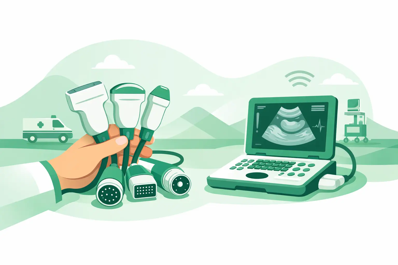
A probe can look correct from across the room and still be unusable on the ultrasound platform in front of you. Effective ultrasound connector identification starts with the assumption that physical similarity is not compatibility. For biomedical teams, ISOs, and repair providers, the objective is to confirm an exact electrical and mechanical match before a replacement probe, cable assembly, or connector-related part is ordered.
A wrong match can cost more than the part itself. It can delay a scheduled repair, create a return cycle, and leave a high-use imaging room unavailable while the correct component is located. This is especially common with legacy systems, where an OEM may have used several connector families across closely related console generations.
Why ultrasound connector identification is not just pin counting
An ultrasound transducer connector carries far more than a simple signal path. Depending on the system and probe design, it may support large element-count arrays, transmit and receive channels, probe recognition, temperature sensing, power, control signals, and shielding. The connector geometry must align precisely with the console port, but matching the shell and approximate pin quantity is not enough.
Two connectors may have a similar rectangular housing, locking lever, or contact layout while using different keying, internal wiring, identification circuits, or channel assignments. A connector from one product family may physically approach the port but still be incompatible or unsafe to force. Conversely, a probe with an unfamiliar connector may be correct when used with a specific OEM adapter or extension cable.
The practical question is therefore not, "What connector does this resemble?" It is, "What exact probe, cable, adapter, and ultrasound platform configuration is this connector designed to work with?"
Start with the system and probe identity
The fastest reliable route to a correct match is usually documentation, not visual comparison. Record the ultrasound system manufacturer, model, and full model variant from the console identification label. A platform family name alone is often insufficient. Software generation, regional version, cart versus portable configuration, and option packages can affect supported probes and accessories.
Then document the transducer itself. The probe label should provide the OEM part number, probe model, serial number, and sometimes a revision or manufacturing code. The part number is the primary sourcing reference because it connects the physical component to the OEM's intended compatibility data. The probe model helps validate the result, but it should not replace the part number when ordering.
If the original label is damaged or missing, collect all available evidence before assuming the probe is unidentifiable. The probe head shape, footprint, frequency markings, cable length, strain relief design, connector shell, and system history can narrow the field. This evidence is valuable, but it should be treated as a cross-reference exercise rather than proof of compatibility.
Separate the probe connector from the system port
Technicians often refer to both mating ends as the connector, which can cause confusion in a sourcing request. Identify whether the replacement need involves the transducer-side connector, the console-side port, an extension cable, or an adapter. These are different service items with different failure patterns.
A damaged probe connector may be part of the transducer cable assembly and may not be economically or technically practical to replace in the field. A damaged console port may be integrated into an input/output board, a connector panel, or a front-end assembly. In other cases, the problem is an intermittent extension cable or adapter rather than either primary mating connector. Defining the failed location prevents ordering a compatible probe when the actual repair requirement is a system-side component.
What to inspect before requesting a replacement
Perform the inspection with the system powered down and the probe disconnected. Do not use contact cleaners, abrasives, tools, or forced mating attempts as a substitute for identification. Connector contacts and shielding structures are easily damaged, and contamination can obscure the actual fault.
A complete record should include the following four items:
- Clear photos of the probe label and the console model/serial label.
- Straight-on, well-lit photos of both connector faces, including pins, sockets, keys, latches, and locking hardware.
- Side and rear photos showing the shell profile, cable exit, strain relief, and any molded markings.
- A concise fault description, such as bent contacts, broken latch, intermittent recognition, image dropout, or no probe detected.
Photographs matter because a connector face alone can hide critical differences. A side view may reveal a keyway position, an offset locking mechanism, or shell depth that separates one connector family from another. If pins are visibly bent, recessed, contaminated, or missing, photograph the condition without attempting to straighten them. The damage itself can help determine whether the issue is limited to the probe, the console port, or both.
Build the compatibility chain
Reliable identification follows a chain: console model to supported probe family, probe model to OEM part number, and part number to connector configuration or approved adapter. Each link should agree before a replacement is approved.
For example, a convex probe may share a similar body style with versions used on several GE, Philips, Siemens, Canon/Toshiba, or Samsung systems. That does not make the probes interchangeable. The same applies to phased-array and linear probes, where comparable clinical applications and frequency ranges can disguise major differences in connector architecture and system recognition.
Adapter use requires the same discipline. Some OEM-approved or platform-specific adapters allow a defined probe family to operate on a compatible system family. Others are physically similar accessories with entirely different mappings. If an adapter is already installed, record its label and part number separately. Never identify the probe solely from the connector visible at the console when an adapter may sit between the original probe interface and the system port.
Legacy equipment needs more evidence, not more guesswork
Older ultrasound systems are where visual matching becomes most risky. Product lines can remain in service for years after original production, and probes may have been repaired, recabled, or acquired from multiple prior owners. A replacement cable may carry a different external label than the original transducer while retaining a specific internal configuration.
In these cases, combine the console details, probe identification, connector photos, and service history. If the system previously used an adapter or a particular probe family, that information can eliminate misleading connector matches. A supplier with part-number-level cross-referencing can use this evidence to distinguish between close variants before a part is shipped.
Common identification errors that create downtime
The first error is relying on the ultrasound manufacturer alone. An OEM name does not define a connector family. Major manufacturers have multiple generations of systems, and those generations may use distinctly different probe interfaces.
The second is matching by probe application. A linear vascular probe, for example, may be available for numerous platforms with nearly identical clinical specifications. Frequency range and footprint describe imaging use, not electrical compatibility.
The third is treating a matching shell as confirmation. Keying, contact count, pin orientation, and internal electronic identification all matter. A connector should never be forced into a port that does not mate freely and correctly.
The fourth is overlooking the system port after a damaged probe connector is found. A bent or broken contact on one side can damage its mate. Before installing a replacement probe, inspect the console port carefully so the new component is not exposed to the same failure condition.
Make the sourcing request actionable
A useful replacement-part request should state whether a complete probe, probe cable assembly, connector repair solution, adapter, or console-side part is needed. Include the system manufacturer and exact model, the probe model and OEM part number when available, and photos of labels and mating surfaces. Add the fault symptom and any known adapter information.
This level of detail lets a specialized imaging-parts supplier cross-reference the part against the correct platform rather than offering a generic connector look-alike. It also makes it easier to evaluate used, refurbished, or select new replacement options based on the actual operational requirement. For urgent repairs, accurate information at the first request is often the difference between a quick quotation and several rounds of clarification.
Meditegic supports this process by sourcing ultrasound probes, transducer-related components, adapters, cables, and other hard-to-find imaging spares against OEM part numbers and verified system compatibility. For equipment in active clinical use, the priority is not finding a connector that appears close. It is obtaining the component that restores the correct probe-to-system relationship with confidence.
When connector details are uncertain, pause the order and improve the evidence. One additional label photo or a clear image of the mating face can prevent a wrong-part shipment and protect the uptime of the ultrasound system you are trying to return to service.