A probe can look intact, pass a quick power-on check, and still be the reason an ultrasound study is unreliable. Ultrasound probe defects often begin as intermittent image artifacts, a small dead zone, or a connection fault that appears only when the cable is moved. For a clinical engineering team or ISO, recognizing the pattern early can prevent repeat exams, service delays, and an avoidable loss of system availability.
The transducer is both a precision imaging component and one of the most heavily handled parts of an ultrasound platform. It is exposed to bending, cleaning chemistry, drops, connector wear, thermal cycling, and repeated patient contact. A structured evaluation helps determine whether the issue is a repairable probe fault, a system-side problem, or a replacement requirement.
What Ultrasound Probe Defects Look Like in Practice
Probe failure does not always create a complete loss of image. More often, the first signs are localized and easy to misattribute to gain settings, scanning technique, or patient conditions. The key is to compare the symptom across presets, scan depths, and - where available - another known-good transducer on the same ultrasound system.
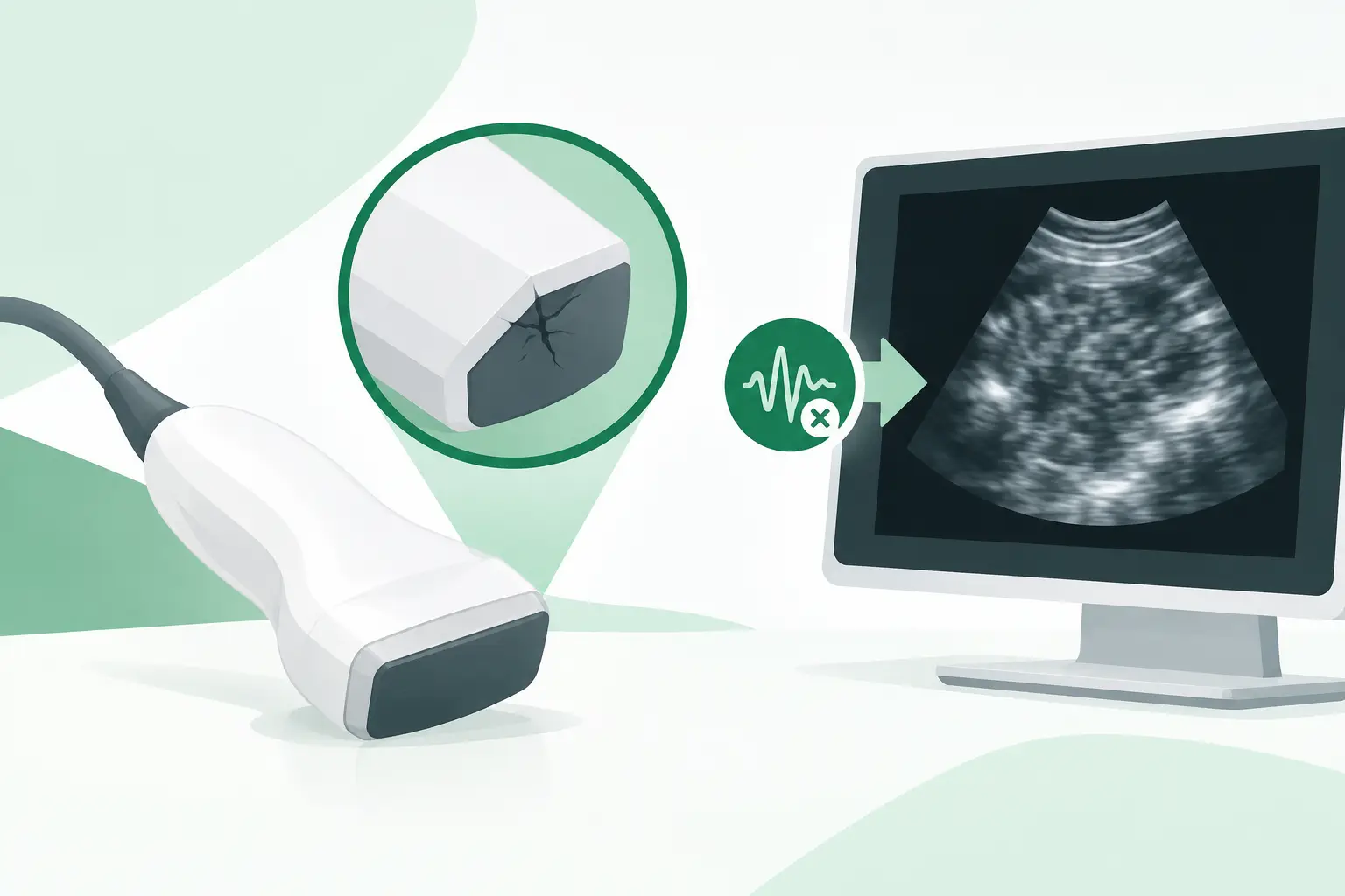
A vertical dropout or dark band extending through the image is a common indication of failed or weak piezoelectric elements. Depending on the probe type and beamformer design, the artifact may be narrow, broad, fixed in position, or more visible at certain depths. Linear array probes can show a particularly obvious missing segment across the near field, while convex and phased-array probes may present as sector nonuniformity or reduced sensitivity in part of the field.
Intermittent image loss during cable movement points more strongly to an internal cable break, strain-relief failure, or connector-related issue. If the image returns when the cable is held in a certain position, do not treat that as a usable temporary condition. Internal conductor damage can progress quickly, and continuing to flex the affected area may turn an intermittent problem into a permanent failure.
Other common indicators include persistent noise, reduced penetration, poor Doppler performance, an error message when the probe is connected, temperature-related warnings, or an inability of the system to identify the transducer. Each symptom narrows the investigation, but none should be evaluated in isolation.
The Main Failure Modes
Element and Lens Damage
The acoustic stack contains the elements that transmit and receive ultrasound energy, along with matching layers, backing material, and an acoustic lens. Element degradation can result from normal wear, impact, fluid ingress, or internal delamination. The clinical consequence may be subtle at first: lower sensitivity, uneven brightness, or a focal area that does not perform as expected.
Lens damage is easier to see but should not be dismissed as cosmetic. Cracks, cuts, punctures, swelling, or surface separation can affect acoustic coupling and image quality. More critically, a compromised lens can create an infection-control concern and allow fluid to enter the probe. Once fluid ingress reaches internal assemblies, the defect may spread beyond the original damaged area.
Cable and Strain-Relief Failures
Cables fail because they are continually wrapped, unwrapped, pulled, pinched, and bent at the same points. The highest-risk locations are usually near the probe head, strain relief, connector boot, and points where the cable is caught in cart hardware or storage brackets.
Cable faults can produce dropout, noise, intermittent probe recognition, or complete signal loss. An external jacket may remain visually intact even when internal conductors or shielding have failed. Conversely, exposed shielding, splits, or stiffness in the cable are direct reasons to remove the probe from routine clinical use until it is assessed.
Connector and Pin Problems
The connector is the electrical and, in some designs, data interface between the transducer and system. Bent, recessed, contaminated, corroded, or damaged pins can prevent the ultrasound platform from recognizing the probe or can produce intermittent imaging faults. Latch wear, damaged housings, and cracked connector boots also matter because they reduce retention and place added stress on internal wiring.
Connector faults should be checked against the system receptacle. A known-good probe that produces the same recognition error can shift the investigation toward the system port, probe board, power supply, or software configuration. Replacing a transducer without this comparison risks unnecessary cost and continued downtime.
Fluid Ingress and Cleaning-Related Damage
Ultrasound probes are cleaned frequently, but not every cleaner, disinfectant process, or soak method is compatible with every probe model. Repeated exposure to an incompatible chemical can degrade the lens, adhesives, cable jacket, markings, and seals. Fluid may then migrate through openings at the lens edge, handle seam, strain relief, or connector.
The practical lesson is specific: follow the transducer manufacturer’s approved cleaning and disinfection instructions for that exact probe family. A process suitable for one endocavitary probe is not automatically suitable for a linear, convex, TEE, or phased-array probe. Store the probe so that the cable is supported and the lens is protected from contact with hard surfaces.
A Practical Fault-Isolation Workflow
Start by documenting the exact system model, probe model, probe serial number, and any displayed error code. Record the affected clinical mode as well. A B-mode-only complaint differs from a Doppler-only degradation, and both differ from a probe that is not detected by the system.
Next, inspect the probe under good lighting. Check the lens for tears, discoloration, swelling, or separation; inspect the housing and strain relief for cracks; and examine the cable and connector for cuts, deformation, pin damage, contamination, or looseness. Do not flex or twist the cable aggressively in an attempt to recreate the problem.
Then test the probe using an appropriate phantom and standardized settings where possible. Compare uniformity, penetration, dead elements, and noise with a known-good probe of the same type. If the system accepts another compatible transducer without issue, the probability of a probe-side defect rises significantly. If multiple probes fail at the same port, investigate the ultrasound system before procuring a replacement.
A qualified probe tester can add objective element-level information, especially when visual inspection and live scanning do not provide a clear answer. Tester results are useful for confirming element dropout and for documenting the condition of a probe before repair, resale, or replacement. They are not a substitute for system-level troubleshooting when recognition or communication errors are present.
Repair or Replacement Depends on the Defect
A damaged lens, cable, strain relief, or connector may be repairable when the internal array and electronics remain viable. Repair can be a sensible route for a current probe model with a clearly defined external failure. The decision changes when there is widespread element failure, repeated fluid ingress, serious internal damage, or an urgent clinical need that cannot wait for a repair cycle.
Replacement selection is not simply a matter of choosing a similar-looking transducer. The exact OEM part number, probe family, connector style, frequency range, array type, and system compatibility must be verified. A GE, Philips, Siemens, Canon/Toshiba, Mindray, Samsung/Medison, Hitachi, or Esaote probe may have visually similar variants that are not interchangeable across platforms or software configurations.
For legacy ultrasound systems, the original transducer may be discontinued through normal channels even though compatible used or refurbished inventory remains available in the aftermarket. This is where part-number-level sourcing is essential. Meditegic supports technical buyers who need exact-match ultrasound transducers and hard-to-find imaging spare parts without losing time to broad, non-verified substitutions.
Preventing Repeat Probe Failures
Most probe damage is not fully preventable, but handling practices have a direct effect on service life. Keep cables off the floor, avoid tight wrapping, use the designated probe holders, and make sure carts do not pinch cables during transport. Protect the connector from impact and contamination, particularly when probes are moved between rooms or stored off the system.
Build probe inspection into preventive maintenance rather than waiting for a clinician to report an artifact. A short inspection of the lens, cable, strain relief, and connector can catch deterioration before it becomes a failed exam or a same-day replacement emergency. When a defect is found, preserve the identifying information and document the failure symptom before sending the probe for evaluation.
A transducer is a clinical imaging component, not an accessory. The fastest path back to dependable scanning is a clear fault record, a confirmed compatibility check, and an exact replacement decision based on the evidence rather than appearance alone.