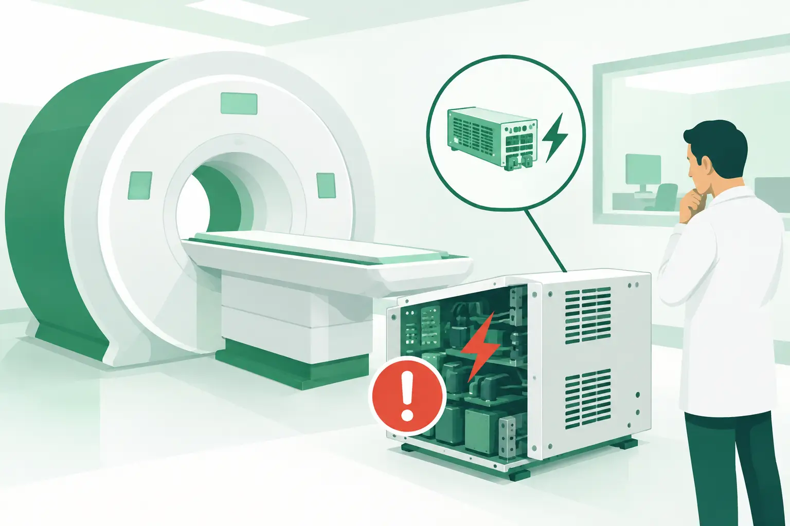
An MRI that will not boot, repeatedly drops a subsystem, or faults only under scan load rarely has a simple power problem. Yet why MRI power supplies fail is often the right question to ask when symptoms point to unstable DC rails, intermittent cabinet faults, cooling alarms, or a system that passes basic startup and fails during demanding sequences. For an ISO, clinical engineering team, or imaging refurbisher, separating the failed power supply from the condition that caused it is what prevents a repeat outage.
Why MRI Power Supplies Fail: The Main Failure Mechanisms
MRI power supplies operate in an environment that combines high electrical load, thermal stress, sensitive control electronics, and long service lives. Depending on the system architecture, a suspected unit may support console electronics, RF equipment, gradient controls, cooling hardware, table functions, or auxiliary subsystems. The correct diagnosis depends on the affected cabinet, OEM design, and exact fault history.
Heat and restricted cooling
Heat is one of the most common contributors to premature power-supply failure. Switching components, rectifiers, capacitors, transformers, and cooling fans all degrade faster when cabinet temperature remains elevated. A blocked air path, contaminated filter, failed cabinet fan, weak blower, or inadequate room cooling can turn a marginal component into an intermittent failure.
The failure pattern matters. A supply that faults after the system has operated for 20 to 40 minutes may be responding to thermal expansion, deteriorated capacitors, or an over-temperature protection circuit. Replacing the supply without correcting the airflow issue can restore operation briefly while leaving the new or replacement unit exposed to the same stress.
Aging electrolytic capacitors
Electrolytic capacitors are frequent wear items in older MRI power electronics. Over time, heat causes electrolyte loss and changes in equivalent series resistance. The supply may still produce acceptable voltage at no load, but its output can sag, ripple, or become unstable when a gradient, RF, or motor-driven subsystem demands current.
This is why a static voltage check alone can be misleading. A rail that appears correct at startup may fail under dynamic load. Symptoms can include random resets, communication errors, sequence aborts, inconsistent boot behavior, or fault codes that initially appear unrelated to the power section.
Input-power events and grounding problems
Facility power quality also affects supply life. Voltage transients, repeated brownouts, phase imbalance where applicable, loose terminations, poor protective grounding, and incorrectly sized upstream protection can damage or destabilize input stages. Sites with a history of electrical work, generator transfers, utility interruptions, or recent facility modifications deserve particular attention.
Not every event produces an immediate hard failure. A surge can weaken input protection devices, rectifier circuits, or control boards, creating a supply that becomes unreliable weeks later. Reviewing the timing of the first fault against site electrical events can narrow the investigation quickly.
Load-side faults that mimic a bad supply
A power supply may shut down because it is doing its job. A shorted load, failing fan motor, damaged cable, degraded PCB, or downstream regulator can pull excessive current and trigger overcurrent or undervoltage protection. In that case, installing another supply may produce the same fault immediately.
Technicians should distinguish between a supply that cannot maintain specified outputs and a healthy supply responding to an abnormal load. OEM service documentation, controlled isolation procedures, measured current draw, and known-good test conditions are essential. MRI equipment contains hazardous voltages and stored energy, so testing must follow the applicable manufacturer procedures and qualified service practices.
Mechanical wear, contamination, and connection faults
Vibration, connector oxidation, loose retention hardware, dust accumulation, moisture exposure, and damaged harnesses can all create intermittent behavior. This is especially relevant in older systems, relocated equipment, and cabinets that have received repeated field service over many years.
A connector can appear seated while a heat-damaged pin, weakened crimp, or oxidized contact produces voltage drop under load. Careful inspection for discoloration, melted housings, arcing marks, swollen capacitors, fan noise, and damaged cable insulation can reveal evidence that fault logs alone will not show.
Symptoms That Point Toward MRI Power-Supply Trouble
Power-supply failures do not always announce themselves with a clear “power supply fault” message. Modern MRI platforms often report the effect on another subsystem: lost communication, a failed interlock, gradient initialization error, RF cabinet fault, or console reboot. The same symptom can result from several causes, which is why the service history is as valuable as the alarm code.
Patterns that justify power-path investigation include recurring faults after warm-up, resets during high-demand scans, multiple unrelated boards reporting communication errors, low-speed or non-starting cabinet fans, visible output ripple, and a fault that follows a specific power module when tested through approved procedures. A complete failure to power up can also originate upstream at a breaker, input contactor, emergency-off circuit, line filter, or facility feed.
The practical question is not simply whether voltage is present. It is whether the correct rail is present, stable, within tolerance, and able to support its specified load. That distinction avoids replacing expensive assemblies on assumption.
A Disciplined Diagnostic Sequence
Start with the exact system configuration and recorded error history. MRI platforms can differ by software revision, cabinet layout, magnet generation, and subsystem options. Record the OEM part number, assembly number, revision, serial information where relevant, and all labels on the suspect module before removing it. A description such as “MRI power supply” is rarely specific enough for correct replacement sourcing.
Next, inspect the operating conditions. Check cabinet temperature, airflow, fan operation, filters, input power, grounding, and visible harness condition. Compare the timing of failures with scan load, room temperature, system warm-up, or site electrical events. These observations often reveal whether the failure is internal to the supply or associated with a load or environment.
Then test according to the OEM service procedure. Confirm input power before condemning the unit, and verify output rails both at startup and under permitted operating conditions. Where documentation allows, isolate downstream loads methodically rather than disconnecting components at random. Confirm whether protection circuits are tripping, whether output ripple is excessive, and whether control or enable signals are present.
For intermittent faults, do not treat one successful reboot as verification. Repeat the conditions that produced the failure, review trend data where available, and determine whether the problem follows temperature, load, cable movement, or a particular module. A short, controlled test plan is usually faster than exchanging multiple boards without evidence.
Replacement Decisions: Repair, Refurbished Part, or Exact-Match Spare
The right corrective action depends on the supply type, available support information, lead time, and the cost of system downtime. Some assemblies can be repaired by a qualified electronics specialist when the failure is limited to serviceable components and the repair can be tested appropriately. In other cases, replacement is more predictable, particularly when the module has extensive thermal damage, multiple degraded components, or an obsolete control board.
A refurbished power supply can be practical for legacy MRI platforms, but only if it matches the required OEM part number and revision requirements. Form factor alone is not enough. Connector pinout, output ratings, firmware or control interfaces, cooling configuration, and board revision can vary within the same equipment family.
Before ordering, provide the equipment model, exact part number from the failed module, clear label photos, fault details, and any known revision constraints. This improves cross-reference accuracy and reduces the risk of receiving a physically similar but electrically incompatible assembly. For hard-to-find MRI parts, Meditegic can support exact-match sourcing through its specialized imaging-parts network, including used, refurbished, and select new replacement options when available.
Preventing the Next Failure
Power-supply reliability improves when preventive maintenance addresses the whole electrical and thermal chain. Keep cabinet airflow paths clear, replace failed cooling components promptly, inspect harnesses and connectors during scheduled service, and investigate recurring facility-power events instead of treating them as isolated incidents. For aging systems, maintaining a record of high-failure assemblies and their revisions helps service teams anticipate sourcing needs before an outage becomes urgent.
When an MRI power supply fails, the fastest path back to scanning is usually not the quickest part swap. It is a verified diagnosis, correction of the underlying stressor, and an exact-match replacement decision that protects the system from the next avoidable shutdown.