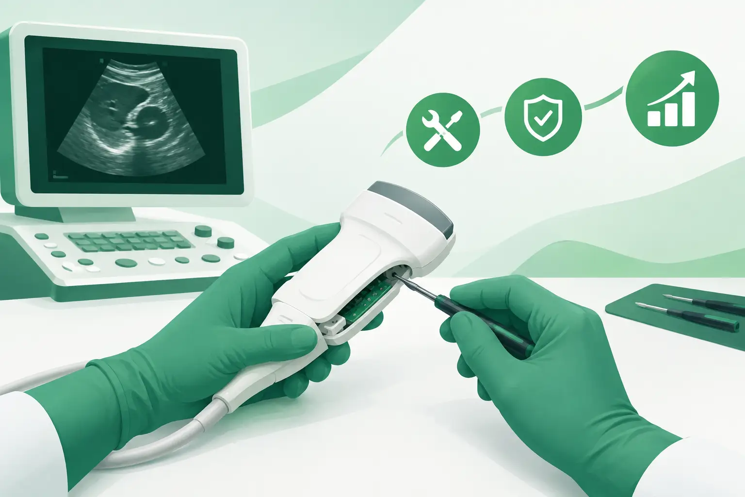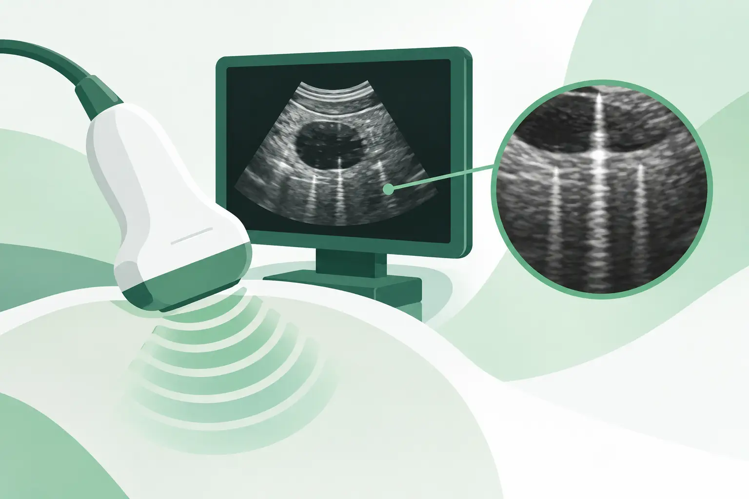
An ultrasound image that suddenly shows a vertical dropout, persistent line, broad band of noise, or reduced penetration often raises the same service question: why transducers develop artifacts even when the scanner itself appears to be functioning normally. The answer is usually physical degradation somewhere in the probe assembly, but the artifact pattern, probe type, clinical preset, and result of a controlled comparison determine whether the transducer is actually at fault.
For clinical engineering teams, ISOs, and ultrasound service providers, this distinction matters. A probe can produce a recognizable image while still having defects that compromise diagnostic confidence. Conversely, contamination, a damaged cable connector, an incorrect system setting, or a scanner channel issue can imitate a failed transducer. Accurate isolation prevents unnecessary downtime and avoids replacing an otherwise serviceable part.
Why Transducers Develop Artifacts Over Time
An ultrasound transducer is an active electromechanical assembly. Its piezoelectric elements convert electrical pulses into acoustic energy, then convert returning echoes back into electrical signals. Those elements operate behind matching layers, an acoustic lens, shielding, backing material, internal wiring, a strain-relief section, cable, and connector. Damage or aging in any of those areas can alter how the probe transmits, receives, or communicates with the ultrasound system.
The most common root cause is element failure or degradation. Each element in a linear, curved, phased-array, or matrix-array probe contributes to a defined portion of the image. When one or more elements lose sensitivity, become electrically open, short, or partially disconnected, the system may display a vertical dark band, a repetitive dropout, reduced uniformity, or poor resolution at a consistent position in the field of view. The appearance varies by probe geometry and beamforming method, so a defect is not always a clean black line.
Mechanical stress is another frequent cause. Probes endure repeated bending near the strain relief, traction on the cable, drops, compression in storage, and impact against bed rails or exam-room fixtures. A cable conductor may fracture internally while its outer jacket remains intact. Intermittent artifacts that appear when the cable is flexed, moved, or positioned at a particular angle are especially suspicious for internal cable or connector damage.
Fluid ingress can accelerate failure. Cracked housings, damaged lens material, compromised seals, and improper cleaning or disinfection can allow moisture to reach internal components. Depending on the location, the result may be erratic noise, broad areas of dropout, unstable images, or progressive failure after the probe has been used for a period of time. A probe approved for a specific disinfection method can still be damaged if chemical concentration, contact time, temperature, or immersion depth falls outside the manufacturer’s instructions.
Artifact Patterns That Point to a Probe Fault
A useful troubleshooting principle is consistency. If an artifact remains in the same relative location on the image while scanning different patients, phantoms, depths, and presets, the transducer deserves close attention. If it follows anatomy, changes with scan angle, or disappears after adjusting gain, focal zones, dynamic range, or frequency, it may be an imaging phenomenon rather than a hardware defect.
Element dropout and dead zones
Dead or weak elements commonly create a narrow vertical dropout in linear and curved-array images. In phased-array probes, failed elements may cause sector-specific degradation, reduced sensitivity, streaking, or incomplete portions of the image. The defect may be more visible at certain depths or frequencies because different transmit patterns and receive apertures are used across presets.
A small element fault does not always make a probe unusable immediately. However, a recurring dropout through clinically relevant tissue can become unacceptable long before the probe stops producing images entirely. For that reason, probe acceptance should be based on image uniformity and intended application, not simply whether the system recognizes the transducer.
Noise, flashing, and intermittent image loss
Random speckle bursts, flashing, unstable image sections, or complete image interruption can indicate a damaged cable, weakened solder joint, shielding failure, or connector-pin issue. These symptoms may occur only when the cable is handled, when the probe is rotated, or after it warms during a longer exam.
Intermittent faults require disciplined testing. If the transducer is manipulated during a live clinical exam without observing a defined test process, it is easy to mistake normal image variation for hardware instability. A phantom or uniform test target makes the change much easier to document.
Surface damage and near-field degradation
A damaged lens or face can cause poor near-field uniformity, localized signal loss, artifacts close to the transducer surface, and reduced coupling. Cuts, gouges, delamination, swelling, discoloration, or areas that feel unusually soft can indicate more than cosmetic wear. The lens is part of the acoustic path, and its condition affects energy transfer into the patient.
Air trapped between the lens and skin can also create dropout, so adequate gel and proper contact must be confirmed before declaring the probe defective. If the artifact persists with good coupling and is fixed in the same image location, physical lens or internal array damage becomes more likely.
Not Every Ultrasound Artifact Comes From the Transducer
Before ordering a replacement, isolate the fault across the full imaging chain. Connect the suspect probe to another compatible port, if available, and test a known-good compatible probe on the original port. If the artifact follows the probe, the probe is the leading suspect. If it remains on one port with multiple probes, investigate the system connector, front-end electronics, or related scanner hardware.
The comparison must be meaningful. Use comparable presets, frequencies, depth settings, gain, and focal-zone placement. Test against a tissue-mimicking phantom when possible. A uniform phantom image reveals fixed bands, weak channels, and sensitivity variation far better than a complex patient anatomy image.
Connector inspection also matters. Bent, recessed, contaminated, corroded, or damaged pins can interrupt signal paths and create artifacts that resemble internal element failure. Inspect only with the system powered down and follow the OEM’s handling guidance. Do not attempt improvised pin straightening, aggressive cleaning, or unauthorized connector repair. Those actions can convert a limited fault into a nonrepairable probe or damage the scanner port.
A Practical Fault-Isolation Workflow
Start by recording the probe model, OEM part number, system model, serial number, clinical application, and exact artifact behavior. Capture representative still images or clips, noting the preset, depth, frequency, and whether the issue changes with cable position. This record supports repair evaluation and prevents a vague “bad image” report from delaying the next step.
Next, perform a visual inspection of the lens, housing seam, strain relief, cable jacket, connector body, and pins. Look for cracks, exposed shielding, flattened cable sections, discoloration, fluid residue, or evidence of impact. Then run the probe through a controlled phantom test and compare it with a known-good probe of the same or compatible type.
Where available, a qualified probe tester can provide element-by-element data on sensitivity, continuity, capacitance, or pulse response. These tools are valuable because subtle array faults can be missed in a basic visual inspection. Still, tester results should be interpreted alongside clinical image behavior. A borderline element result may be tolerable for one application and unacceptable for another, such as vascular, small-parts, cardiac, or high-resolution musculoskeletal imaging.
If replacement is required, exact identification is essential. Ultrasound probes that look similar may differ in frequency range, array configuration, connector keying, software compatibility, or application support. The safest procurement record includes the OEM part number from the probe label and the ultrasound system model, rather than relying on a marketing name alone. For discontinued or difficult-to-source probes, Meditegic can help cross-reference the exact part number and locate compatible used, refurbished, or select new replacement options.
Preventing Repeat Transducer Artifacts
Most preventable probe failures begin with handling and reprocessing practices rather than a sudden internal defect. Avoid lifting or moving the scanner by the cable, sharply coiling the cable, hanging probes where they can strike equipment, and storing them under sustained cable tension. Use approved holders that support the probe head and protect the lens.
Cleaning and disinfection protocols should match the probe’s approved use category and manufacturer instructions. The practical risk is not only using the wrong chemistry. Excessive exposure time, incomplete rinsing, high heat, or immersion beyond the approved level can degrade lens materials, seals, and adhesive bonds. Routine visual inspections after reprocessing can catch early lens and housing damage before it develops into a recurring image-quality complaint.
When an artifact first appears, remove the affected transducer from clinical use if image quality is questionable, document the fault, and compare it under controlled conditions. Fast, evidence-based isolation protects the scanner, reduces repeated troubleshooting, and gives the service team the part identification needed to restore dependable ultrasound imaging with confidence.